Hi. I’m attempting to change the crossover points of a 4-way tube crossover that I didn’t build.
I thought it would be a simple enough project but not so.
The filter stages are preceded by a common cathode stage that provides 20dB of gain.
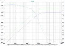
I’ve used TCJ Filter Designer to provide resistor and capacitor values. Here’s an illustration of the 35Hz filter:

The curve shows the output down about 7dB at the 35Hz crossover point.
From what I’ve read I’d be expecting 3dB.
Where does this 7dB number come from?
When I rebuilt all 4 stages the crossover frequencies measured at 7dB down from the peak response were wrong.
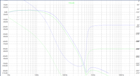
I’ve tried a lot of simulation to try and understand why. This chart shows the raw 14kHz plot in blue (-7dB at 14kHz as designed) and the amplified plot in green (-7dB at 9kHz).

Why the difference? Why isn't there a constant 20dB difference across the frequency range?
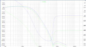
Same with the 35Hz Low Pass filter with the curves shifted with the peak of the pass band on top of each other:

I fear I'm missing something fundamental here.
Thanks!
I thought it would be a simple enough project but not so.
The filter stages are preceded by a common cathode stage that provides 20dB of gain.
I’ve used TCJ Filter Designer to provide resistor and capacitor values. Here’s an illustration of the 35Hz filter:

The curve shows the output down about 7dB at the 35Hz crossover point.
From what I’ve read I’d be expecting 3dB.
Where does this 7dB number come from?
When I rebuilt all 4 stages the crossover frequencies measured at 7dB down from the peak response were wrong.
I’ve tried a lot of simulation to try and understand why. This chart shows the raw 14kHz plot in blue (-7dB at 14kHz as designed) and the amplified plot in green (-7dB at 9kHz).

Why the difference? Why isn't there a constant 20dB difference across the frequency range?
Same with the 35Hz Low Pass filter with the curves shifted with the peak of the pass band on top of each other:

I fear I'm missing something fundamental here.
Thanks!
The filter presume a zero impedance source.
Probably the output impedance of the pre-amp gives the extra loss.
Mona
Probably the output impedance of the pre-amp gives the extra loss.
Mona
The filter -3dB point is not necessarily the filter corner frequency. It is for a single-pole filter or a Butterworth filter, but not necessarily for other filter types.
That filter is a third-order Sallen and Key low pass filter - I'd recommend using a higher gain dual triode like a 12AX7 for more accurate response for a higher order filter like this - 1st or 2nd order Sallen/Key are less critical.
The 6N1P has gain of 35, so as a follower it doesn't have exactly unity gain, only about 0.97, and this will affect the filter response noticeably.
You'll find design aids for Sallen/Key filters all over the web.
The filter should be preceded by a low output impedance section, such as cathode follower.
Thanks Mona, Mark and DF96 for your replies.
The crossover I'm modifying does indeed use 12AX7s. I should have mentioned that.
The 12AX7 datasheet shows the anode resistance at 250V of 62.5K. That'll be in parallel with the 100k anode resistor.
I assumed a source resistance of 50k and added that to my simulation sources. The results explain some of the variation in crossover frequency of the full stages with the filters preceded by the common cathode stage.
Ideally, the filters should be driven from a low impedance source but my brief is to change the crossover points and not do anything that might change the sound quality.
I can compensate for the high source resistance in the low pass filters by reducing the resistance of the first resistor in the filter. I'll have to think about the high pass filters.
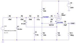
A much bigger contributor to my problems with the crossover points is that the crossover I'm working on uses 100k bias resistors instead of the 2M resistors specified in the TCJ Filter tool. Here's the 35Hz low pass schematic:

Here's a comparison of the 2M bias resistors (green trace) and 100k bias resistors (blue trace).

The preceding capacitor and the 100k bias resistors act as an additional high pass filter, reducing the level by around 20dB and shifting the crossover frequency.
I can reluctantly live with the design compromises but I need some certainty in selecting the filter resistor and capacitor values.
Unfortunately, I'm not getting much agreement between the simulated and measured results so the simulation isn't much help there.
Dave.
The crossover I'm modifying does indeed use 12AX7s. I should have mentioned that.
The 12AX7 datasheet shows the anode resistance at 250V of 62.5K. That'll be in parallel with the 100k anode resistor.
I assumed a source resistance of 50k and added that to my simulation sources. The results explain some of the variation in crossover frequency of the full stages with the filters preceded by the common cathode stage.
Ideally, the filters should be driven from a low impedance source but my brief is to change the crossover points and not do anything that might change the sound quality.
I can compensate for the high source resistance in the low pass filters by reducing the resistance of the first resistor in the filter. I'll have to think about the high pass filters.
A much bigger contributor to my problems with the crossover points is that the crossover I'm working on uses 100k bias resistors instead of the 2M resistors specified in the TCJ Filter tool. Here's the 35Hz low pass schematic:

Here's a comparison of the 2M bias resistors (green trace) and 100k bias resistors (blue trace).

The preceding capacitor and the 100k bias resistors act as an additional high pass filter, reducing the level by around 20dB and shifting the crossover frequency.
I can reluctantly live with the design compromises but I need some certainty in selecting the filter resistor and capacitor values.
Unfortunately, I'm not getting much agreement between the simulated and measured results so the simulation isn't much help there.
Dave.
- Status
- Not open for further replies.