hello,
I have an el84 stereo SE that uses 2x halves 12aux7 for each channels gain stages.
I'm adding another 2 half gain stages in front for guitar and would also like to add a tube tremolo, possibly a circuit to each of the channels independently controlled stereo effect.
I'm trying to find a simple schematic with depth and speed control that uses preferably one half of a 12ax7/ecc83 because i have the tubes and sockets already and doesn't use any pots larger than 1meg because it is the largest I have.
it would be good if if the schematic shows where it would connect into the part of the SE stage to effect volume,
If any one knows of any or links that would be great thanks, if worse comes to worse i have some 6sn7 and some 6sl7 but im worried they will draw more current and i dont want to have to swap transformers,
cheers
> find a simple schematic
I think you have too many features to also be "simple".
SE trem exists but most are lame.
Stereo trem adds real complication.
I hate to make money for Banjo Center, but they have $59 pedals which do trem better than about any SE trem. May be $79 for stereo. But look in the Pre-Owned Gear display, ask for scratch/dent, ask if other customers have tried to unload trem pedals....
hello,> find a simple schematic
I think you have too many features to also be "simple".
SE trem exists but most are lame.
Stereo trem adds real complication.
I hate to make money for Banjo Center, but they have $59 pedals which do trem better than about any SE trem. May be $79 for stereo. But look in the Pre-Owned Gear display, ask for scratch/dent, ask if other customers have tried to unload trem pedals....
I've got ss optical tremolos i've built and work fine but because the amp is so old im wanting to keep to old technology. I have this simple schematic that uses an octal. i was hoping to find something similar that uses a 12ax7 9pin novel base because they are already installed.
the two channels operate independently (like two seperate mono se amps) so i think it just involves same as build two simple tremolos, one for each channel.
then just connecting each one individually to each grid on the el84's im guessing.
surely cant cause too many problems because the input signal has been split and separated 3 stages before tremolo?
Attachments

You are trying to change the gain within a feedback loop.That doesn't work, the change of gain is compensated by the feedback.then just connecting each one individually to each grid on the el84's im guessing.
surely cant cause too many problems because the input signal has been split and separated 3 stages before tremolo?
Perhaps it could function like this.But still more or less within the loop.
Mona
Attachments

Last edited:
sorry the schematic i posted is original schematic from an early ampeg rr.You are trying to change the gain within a feedback loop.That doesn't work, the change of gain is compensated by the feedback.
Perhaps it could function like this.But still more or less within the loop.
Mona
posted to show PRR example simple tube tremolo because I think he may have miss understood what i wish to try create .
what i typed about adding another gain stage was just to give an overview of the whole project. sorry for confusion i will post schematic very simalar to what i am meaning to try to re-create, cheers
*first picture.......here is very similar schematic to stereo amp to add two separate tremolo circuits to.
*second picture.....
-original schem early ampeg trem 6SL7 tube connected to grid (on left).
-original schem late model ampeg trem circuit using 12ax7 and photo coupler conected series to first pre tube output signal path (on right)
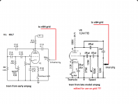
*third picture.....
-original schem early ampeg trem 6SL7 tube connected to grid (on left).
-original schem late model ampeg trem circuit using 12ax7 adjusted for possible use on SE el84 grid providing B+ voltages are equivalent? (on right)
If any one can see why the simplified 12ax7 circuit will not work on SE el84 grid, please tell why so i will be very greatful not to wire and have to re wire fault.
( --notes on using effect---am thinking to use effect very subtle not strong..........maybe one channel will be set do low guitar freq trem at half speed and other channel for high guitar freq at double speed.....not sure..... or maybe just both slightly off speed. to think of ideas)
*second picture.....
-original schem early ampeg trem 6SL7 tube connected to grid (on left).
-original schem late model ampeg trem circuit using 12ax7 and photo coupler conected series to first pre tube output signal path (on right)
*third picture.....
-original schem early ampeg trem 6SL7 tube connected to grid (on left).
-original schem late model ampeg trem circuit using 12ax7 adjusted for possible use on SE el84 grid providing B+ voltages are equivalent? (on right)
If any one can see why the simplified 12ax7 circuit will not work on SE el84 grid, please tell why so i will be very greatful not to wire and have to re wire fault.
( --notes on using effect---am thinking to use effect very subtle not strong..........maybe one channel will be set do low guitar freq trem at half speed and other channel for high guitar freq at double speed.....not sure..... or maybe just both slightly off speed. to think of ideas)
Attachments


Last edited:
If you modulate the voltage on the control grid the current in the tube change but hardly the gain.By changing the current the working point shift up and down away from the center condition, making the amp clipping.Sort off distortion vibrato.If any one can see why the simplified 12ax7 circuit will not work on SE el84 grid, please tell why so i will be very greatful not to wire and have to re wire fault.
A voltage devider modulated by the vibrato in the signal path changes the amplitude without shifting the DC-condition of the circuit.
Something like this,
Mona
Attachments

thankyou,
the tremolo circuit is designed around 330vdc.
my amp can supply only 110vdc from selenium rectifier.
do you think oscillater will work on 110vdc or will i have to change plate resistor and cathode resistor to make work?
the tremolo circuit is designed around 330vdc.
my amp can supply only 110vdc from selenium rectifier.
do you think oscillater will work on 110vdc or will i have to change plate resistor and cathode resistor to make work?
- Status
- Not open for further replies.
- Home
- Live Sound
- Instruments and Amps
- tube tremolo schematic for SE