Did anybody ever try to feed two bridge rectifiers from one tapped, toroidal transformer secondary? I.E. two separated unregulated power supplies sharing the secondary side of one toroidal transformer? The idea would be to get a better channel separation then with a shared power supply, but avoiding an additional transformer.
This is possible provided that the circuits you mean to feed are independent to each other.
You should use only one bridge rectifier, by connecting the side pins of the transformer, followed by e.g. a 1000uF capacitor and then an half wave rectifier (just one diode directly from the c.t. pin) still followed by 1000uF.
In such this way you'll obtain 1/2V(out) for the latter and V(out) for the former. The ground has to be referred to the negative pin of the bridge rectifier
Obviously, precautions have to be taken into account about the different currents demands and in any case it is mandatory to stay within the transformer's specs.
I used this combination in a satisfactory way, in two independent fed circuits of a hybrid amp.
Not going to help crosstalk. Pay attention to your cap bank and how the VAS and IPS are fed. Many use a resistor and cap, I have switched to a pi filter. For example, the 56V rails on my amp fed a 47 Ohm resistor with a 100u cap on the VAS side for each channel. I replaced it with two 22 Ohm resistors and two 100u caps. Dropped ripple by 8 times without dropping the rails as much as a cap multiplier.
If you think power supply ripple is causing crosstalk, improve the main filter bank. Bigger single rectifier and increase the bank. The "stiffer" the supply, the less either signal will modulate the rails. Physical grounding and overall layout are more important.
Crosstalk is way over-rated. Anything better than about 60 dB is more than enough. There are many places where real sonic improvements can be made. That is not one of them. On another thread, someone wanted to cut up his headphone cable to plug into a balanced plug thinking less crosstalk or some other magic. Well, go play an old Beatles "two channel" as they were not stereo and see how horrible no crosstalk sounds. It used to be common to have a frequency dependent crosstalk adder in phone amps before the "purity " BS started in the glossy mags.
Twin mono amps makes sense once each channel weighs 40 Lbs or more. Just so you can lift it. Fine for some ego amps. Tell me, does the crosstalk in a Benchmark bother you? Single SMPS. Try to find a better non-sounding amp for any amount of money. Have money to spend? Buy better speakers. When you have bought the very best in the world, the weakest link will still be the speakers, not if your crosstalk is improved from 86 to 89 dB.
I meant something like shown in the attached schematic. While drawing it, I got a feeling in my stomach, that splitting those high charging current paths to the capacitors might do more harm than use. Combining it to one single supply and putting the focus on PSRR of the amp might be the better idea and would also ease the connection of the protection circuit.
Attachments
I think you would have a stiffer supply if you just used 20,000 on each rail and pay attention to physical layout. Get additional caps closer to the draw.
Of course, good current mirrors and constant current sources in the IPS and VAS help. I have not studied the spreader and driver stage. In my last re-cap, I went from big cans ( I could not get in less than 1000 qty) to a bank of 6800's. Lower ESR, but I can't prove it matters much. Sounds wonderful, but it did when I first built it. Do be sure you select the bridge for the inrush current. Many are a bit small.
Of course, good current mirrors and constant current sources in the IPS and VAS help. I have not studied the spreader and driver stage. In my last re-cap, I went from big cans ( I could not get in less than 1000 qty) to a bank of 6800's. Lower ESR, but I can't prove it matters much. Sounds wonderful, but it did when I first built it. Do be sure you select the bridge for the inrush current. Many are a bit small.
The common supply has also the advantage, that the area which is spanned by the capacitor charging pulse currents can be made smaller and this would avoid spreading 100Hz harmonics magnetically.
No, this symmetrical combination departing from c.t. is not good for feeding two PSU...it is not possible to obtain a common ground (reference) shared between the two bridge rectifiers. You should think to a more complex work.
I can imagine doable (but I never tried it) with two distinct linear regulators in a voltage doubler and ordinary circuit.
A single diode bridge would be needed, which the "real" ground of shared between the 2 circuits: the c.t. pin would be as the "virtual" ground and directed to a first regulator (to the smaller voltage, ~1/2V), while the positive cycle from top diodes would go to a second regulator (to the higher voltage, ~V).
The negative cycle from the lower diodes would be shared for both, as said, and that is the ground reference.
Then, to further split each psu you may use an opamp rail splitter circuit if the current demand is rather low.
Anyway, il all seems to be tricky. The better thing is to opt for a dual secondary transformer or you can also separate by yourself the c.t. wires (e.g. 2 or 4 usually) if you have physical access to this...
Edelbaster,
It looks like you're trying to block the path for circulating currents between the two channels. Some improvement in channel separation should result, at least in theory. In my opinion, this method could be more effective for switching amplifiers (rather than linear ones), as the bus pumping due to one Ch1 wouldn't affect Ch2, as their related rectifier diodes are facing each other. Then there's the contribution of the separate capacitor banks.
It looks like you're trying to block the path for circulating currents between the two channels. Some improvement in channel separation should result, at least in theory. In my opinion, this method could be more effective for switching amplifiers (rather than linear ones), as the bus pumping due to one Ch1 wouldn't affect Ch2, as their related rectifier diodes are facing each other. Then there's the contribution of the separate capacitor banks.
Hallo Edelbastler,your circuit can work, but as the two grounds have slightly different currents they differ in voltage. not much, but
it will have a bad influence at the input. You need to make a groundlift with ca 10 Ohms or so at both channels .
Happy Basteln! Ingo
it will have a bad influence at the input. You need to make a groundlift with ca 10 Ohms or so at both channels .
Happy Basteln! Ingo
It is definitely not a good idea to use the two rectifiers. Using two rectifiers on one tapped secondary leads to a big ground loop, which starts at the transformer tap and ends (at least) at the signal source feeding the amplifier. This loop partially carries the capacitor charging spikes and because it is big enough, it will also show substancial inductive spikes induced by the magnetic field of the charging pulses. (see picture "two rectifiers.jpeg").
With a shared power supply, the loop starts at the signal starpoint and ends at the signal source. Assuming correct wiring, the loop will not carry charging pulses nor be inductively coupled to their magnetic fields (one rectifier.jpeg).
I will go for a shared supply with 2x2x10mF. Thank´s for reflecting upon my idea.
Attachments


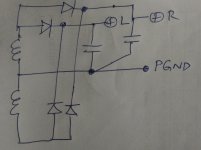
Edelbaster, I have redrawn your circuit (+ve supply only) and I still see no problems (picture). The pre-GND needs to connect to the power GND in such a way that the connection does not involve heavy currents, including the return currents from the speakers.
Your first layout in the above post looks incorrect to me, as there is an impedance between the LRGNDs and the centre tapping. The rectifiers and capacitors are supposed to be as close to the transformer as possible, in order to keep this impedance really close to zero.
Your first layout in the above post looks incorrect to me, as there is an impedance between the LRGNDs and the centre tapping. The rectifiers and capacitors are supposed to be as close to the transformer as possible, in order to keep this impedance really close to zero.
Attachments
Of course, your are right. I took the wrong start in my thoughts. My idea startet from a dual mono block with a single transformer 🙂
In fact there is no need to separate the capacitors physically.
In fact there is no need to separate the capacitors physically.
Also, the power must enter the amplifier board from near the output, with an almost direct short between SPKGND and PGND. Pre-amplifier inputs may enter from the opposite side of the board. This way all the power is on one side, with all line-level on the other.
Hi Ingo!Keine Widerrede von mir! servus ingo
no contradiction by ma ! bye ingo
I guess, it should be right now 🙂
INGNDx ... GND for input and feedback
HTGNDx ... GND for the local bypass-capacitors on the amplifier board
OUTGNDx ... GND to Load-Connection
ProtGND ... GND for the protection circuit and the output relays. The protection circuit will have its own small power supply.
Kind regards/Liebe Grüße from Vienna/aus Wien
Robert
Attachments

no good.....if you want two bridge rectifiers, use a two separate secondary traffo type....Did anybody ever try to feed two bridge rectifiers from one tapped, toroidal transformer secondary? I.E. two separated unregulated power supplies sharing the secondary side of one toroidal transformer? The idea would be to get a better channel separation then with a shared power supply, but avoiding an additional transformer.
https://pinkfishmedia.net/forum/proxy.php?image=https%3A%2F%2Fi.imgur.com%2F9y4Ar08.png&hash=40d1eb254559a6be9a0342aa1028682a
INGNDx ... GND for input and feedback
HTGNDx ... GND for the local bypass-capacitors on the amplifier board
OUTGNDx ... GND to Load-Connection
ProtGND ... GND for the protection circuit and the output relays. The protection circuit will have its own small power supply....
In my opinion, only the speaker GND and (maybe protection) must be near the PGND and power supply, all others are best connected to PGND on the PCB, at a single place.
What is the conclusion? That there is no advantage to schema in #15?
No verdict, just opinions (with explanations, as far as possible). It's the OP's call.
Why, is it not good?no good.....if you want two bridge rectifiers, use a two separate secondary traffo type....
https://pinkfishmedia.net/forum/proxy.php?image=https%3A%2F%2Fi.imgur.com%2F9y4Ar08.png&hash=40d1eb254559a6be9a0342aa1028682a
- Home
- Amplifiers
- Power Supplies
- Two bridge rectifiers