• WARNING: Tube/Valve amplifiers use potentially LETHAL HIGH VOLTAGES.
    Building, troubleshooting and testing of these amplifiers should only be
    performed by someone who is thoroughly familiar with
    the safety precautions around high voltages.

UL + CFB ratio for a PL36 tube?

Hi folks,

I've got a stash of these tubes and would like to build something new - a SE the PL36 in ultra linear mode and cathode feedback.

I can wind my own custom OPT in any ratios, but I lack the knowledge to calculate the optimal UL and CFB ratios for this tube.

In pentode mode, the datasheet claims
Gm - 14mA/V
g2/g1 gain - 5.6
Ra - 5k
 
Not SE and no UL: EL36 PP pentode with 20% CFB. IIRC around 440V anode, 150V G2, ca. 50W out. No particular reason for the percentage: leftover OPTs from a previous project. 6k6 to 6 ohm connected to 4 ohm speakers. I should take some time to fine-tune the driver, as the CFB requires quite some swing, but never felt the need for that. I like it as it is.

The EL36 in triode is sometimes referred to as a poor man's 2A3. I'd probably start an SE project at a similar OP: 250V, 50mA and a 2k5 load. My guess is that you don't need a lot of CFB when using UL. Pentode and screen drive need feedback to improve damping. UL as well, just less.
 
Hey, thanks for sharing!

Do you have measurements of your amplifier? In PP you get even harmonic cancellation, I wonder how much of them will be left in SE mode.

I'm thinking if I could do it with CFB only.

One PP amplifier I liked a lot, had lots of microdetail like a well built SE amp. It had GU50s in pentode mode, UL + CFB. So I'm tempted to build a PP version with CFB as well.
I'm searching to build an amp that has the refinement and bass behavior of a PP, but the subtleness and speed of SE.
 
Forget about UL, it was a fashion. Instead of UL you need to bootstrap screen grids to cathodes for lower distortions. Even 0-16 Ohm secondary taps with grounded 4 Ohm tap make a huge sonic difference, but 10-20% should be better.
 

Attachments

  • 16700414_1356523561072608_7781163404652396171_o.jpg
    16700414_1356523561072608_7781163404652396171_o.jpg
    823.3 KB · Views: 710
Member LAZAROIU has posted triode curves with a simulated operating point yielding 10% second harmonic and 0.07 third (other odd order harmonics also very low). Class A triode push-pull should give very clean sound without needing feedback (if the simulation is realistic).
 
Wavebourn, I see only secondary to cathode type of ncfb connection, while g2 seem to be directly connected to the power supply rail. Are you talking about the input tube connection between g2 and the cathode?

Piano3, thanks for sharing this info. 10% of 2nd harmonic (at what power level) is definitely a no-go for a SE, but the PP option is tempting!
 
Forget about UL, it was a fashion. Instead of UL you need to bootstrap screen grids to cathodes for lower distortions. Even 0-16 Ohm secondary taps with grounded 4 Ohm tap make a huge sonic difference, but 10-20% should be better.

Wavebourn I like your inputs. Me too have got a large stash of PL36. The schematics reflects this post (#8105) of November 2017, right ?

I plan a similar amp, long-term work, nothing urgent, I have 20 more years to build it 🙂 My question is, what was the input impedance of the OPT ?
 
Wavebourn, I see only secondary to cathode type of ncfb connection, while g2 seem to be directly connected to the power supply rail. Are you talking about the input tube connection between g2 and the cathode?

I was talking about output tubes; I meant that UL is contrary to what is better, to bypass G2 to cathode. However, in that particular amp I just powered G2 from MOSFET voltage regulator, is is still better than UL.


Wavebourn I like your inputs. Me too have got a large stash of PL36. The schematics reflects this post (#8105) of November 2017, right ?

I plan a similar amp, long-term work, nothing urgent, I have 20 more years to build it 🙂 My question is, what was the input impedance of the OPT ?

I used 4k P-P transformers made by Schumakher for ADA Depot.
 
Wavebourn, I see only secondary to cathode type of ncfb connection, while g2 seem to be directly connected to the power supply rail. Are you talking about the input tube connection between g2 and the cathode?

Alex, the fact that g2 has its own supply and is not connected to the OPT it doesn't mean that it automatically works in pentode mode once you connect the CFB. In the latter case it is UL operation indeed which Crowhurst used to call modified UL an it definitely is better than the traditional one. You need to refer g2 directly to cathode in AC if you want pentode by means of a capacitor for example.
So you can have UL but a different and more convenient g2 supply without an OPT with tertiary winding.
I have never tried the bootstrapping suggest by Wavebourne but it looks very interesting. I think I' ll give it a go as soon as I have time.
 
g2 swinging together with the cathode? That's clever! I guess you have to power g2 using a current source?

What about coupling it AC using a transformer to have different cathode to g2 swings?

I guess I'll dig myself into Crowhurst papers once more.
 
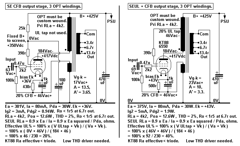
By immersing myself into Patrick Turner's website once again, I stumbled at the following:


Some inspiration. Thanks Patrick!

Another though. If one wants to go for UL, how much worth it would be to interleave primary layers and UL in a way to decrease leakage, like it should be done for CFB layers.
 
Last edited:
Forget about UL, it was a fashion. Instead of UL you need to bootstrap screen grids to cathodes for lower distortions. Even 0-16 Ohm secondary taps with grounded 4 Ohm tap make a huge sonic difference, but 10-20% should be better.

Mr. Wavebourn,

I would like to know more about your dismissal of UL as a fad, but it probably needs another thread so it does not distract from this one. With your agreement I intend to start one.

The schematic for your Hercules amp is of great interest and you have posted it several times. I would like to build it, but your scratchy drawing is so hard to read and understand that I’m hesitant to try follow it. Would you kindly point me to a better drawn schematic of Hercules?
 
Hi folks,
I've been pecking on LTSpice for a few hours, simulating different conditions on different ways to try EL36 / 6CM5 into a PP class AB output stage.
For example, swinging 35V into 10R secondary load (61W), 1.6k p-p load 50% to 50% shared between anode and cathode (CFB), inluding separate 50% UL windings, cross-coupled to the screen grids, separately biased for g2 at 200V
I'm monitoring g2 peaks, watching for g1 current,
However, at such low loads, the tube's cathode current is peaking at 600mA, whereas 200mA absolute max are mentioned within the datasheets. What would happen when cathode current is exceeded?
I'm also experimenting with triode mode, or still pentode mode with no separated UL windings, with a higher load such as 6.6-7k, B+ of 440V and 200V g2 voltage, similar to the conditions member @Parafeed813 recommended
I'm kind of attempting to explore the limitations of this tube, hence needing your advice on this one.
I'm aware 60W output power would melt these tubes, but I'm curious of sweet tuning a good operation headroom with little crossover distortion as possible. In reality, I'm in need of 30W output power,

G2 peaks are rated at 21mA Rms, so that stands for 0.08W Pdiss

What kind of regulator would you recommend for g2? Could a series voltage regulator work out just fine? I'm not pretencious over tube regulators, it could be a solid state one.
 

Attachments

  • PL36.png
    PL36.png
    22.3 KB · Views: 137
The Philips (and others) datasheet mentiones an output power of 45 W, albeit at a plate to plate load of 3k5, 300 V plate voltage and 150 V screen voltage. Hence, 60 W aren't that utopic. The issue is the lower plate load. Increase both the load and voltage to achieve 60 W output power.

Best regards!
 
Yes, Kay, your answer is quite reciprocal. However, I'm also puzzled by the numbers of anode voltage and g2 voltage limitations, so you see, from this point of view I'm looking for the best load possible.
The alternative option already successing in simulating is the 6.6k a-a primary load, with 20% CFB instead of 50%, just like @Parafeed813 recommended, only that a higher g2 voltage was needed.
 
I'm aware 60W output power would melt these tubes

Not necessarily. I drew close to 70W from a pair with a 3,5k plate to plate load a couple of years ago. I can't say how long they would last but there was no red plating or anything. That was a prototype output stage for a bass guitar amp but one of the amps I use frequently in my hifi system is also a PL36 PP with CFB, though only 6W or so as it runs in class A with triode-wired output tubes.

Here's some information about high power amps with EL36:
http://www.chambonino.com/modify/mod1.html
 
@Fuling
70W! Dat gona rock da haus! :rofl:Okay! It is definitely a tank tube, can be abused. Judging by your findings, cathode current matter should not be needed for discussion then.

And here's a quote from Patrick Turner repot of Pd from his website.


Everyone worries about 6CM5 or EL36 idle Pda but it seems max Pda = 17.5W and max Pdg2 = 3.5W
so total max Pda+g2 = 21W. I found the anode did not glow dull red until Pda = 28W.
The idle condition for triode was OK with Ea = Eg2 = 375V with Ia+Ig2 = 50mAdc, so Pda+g2 =18.75W.


http://www.chambonino.com/modify/mod1.html
Many thanks for that link, I've been looking for it!
 
With G2 rated max 250V and very happy at 150V in pentode mode drawing 19mA at max power in push-pull , 375V is pushing the luck in the long term . And I don't think somebody measured the current in this situation . For SE could work , as the current difference from idle - full power is much lower
 
A friend of mine got 25W @ 8 ohms from an OTL output stage with 6x PL36 so they can definitely deliver current when being asked to.
1,6k pp seems like and excellent plate load for two pairs for PL36 if the transformers can handle 90+ watts.