Hello.
Inquiring if any one has used common mode chokes in crossovers, especially for low pass filters.
Given the expense of "audio" quality core and air coil crossovers, could a common mode choke ordinarily used to filter line noise in SMPS supplies substitute.
Some are rated to 10 amps or more and tested at 10KHz.
So a 500uH common mode choke wired in series yields 1.0mH at 5 amps current.
Thanks
Wade
No - if you wire the common-mode choke as a normal kind of choke you'll saturate the core way, way prior to reaching the rated current. There are no free lunches.
Bigun showed a trick that by flipping phase of second leg of CMC, the DC magnetic field is cancelled and it won't saturate - yet retains the inductance property you want. Sure you lost the common mode rejection but that's not what we wanted anyway. I was asking the same thing as I have a Coilcraft CMC that is 20mH per leg and is quite compact.
I'd be interested in such a trick as it would appear to overturn some or perhaps all the laws of electromagnetism. Do you have a link to it?
I'd be interested in such a trick as it would appear to overturn some or perhaps all the laws of electromagnetism. Do you have a link to it?
http://www.diyaudio.com/forums/solid-state/212342-esp-p3a-layout-20.html#post4759269
No, see post #2; if 'simple tricks' worked the we would already be buying very small, light inductors from all the normal outlets...
(tricks with such small core CSA only 'work' while measuring at uselessly-low current. But transformer/inductor core design has been a defined science for over 150years now)
(tricks with such small core CSA only 'work' while measuring at uselessly-low current. But transformer/inductor core design has been a defined science for over 150years now)
I have not tried it yet but I think Bigun may know a thing or two. Obviously it worked for his dual rail PSU with lots of DC current. It's not new - just called a differential mode choke.
Bigun's description of cancellation between the two sides fits the normal use of a CM choke, in this mode the inductance is quite small, just leakage. Certainly not the high common-mode inductance shown in the DS for such chokes.
There's nothing special about a "common mode choke", just a configuration that responds to a common mode signal, whatever that may be in the given application.
All ordinary speaker current flows equally in each cable conductor, so a pair of windings on a single core can be configured to use the available coil inductance, or to cause a net zero effect. Not withstanding discussion of actual common mode signals such as RF picked up onthe cables from external sources, this is just a choke.
All ordinary speaker current flows equally in each cable conductor, so a pair of windings on a single core can be configured to use the available coil inductance, or to cause a net zero effect. Not withstanding discussion of actual common mode signals such as RF picked up onthe cables from external sources, this is just a choke.
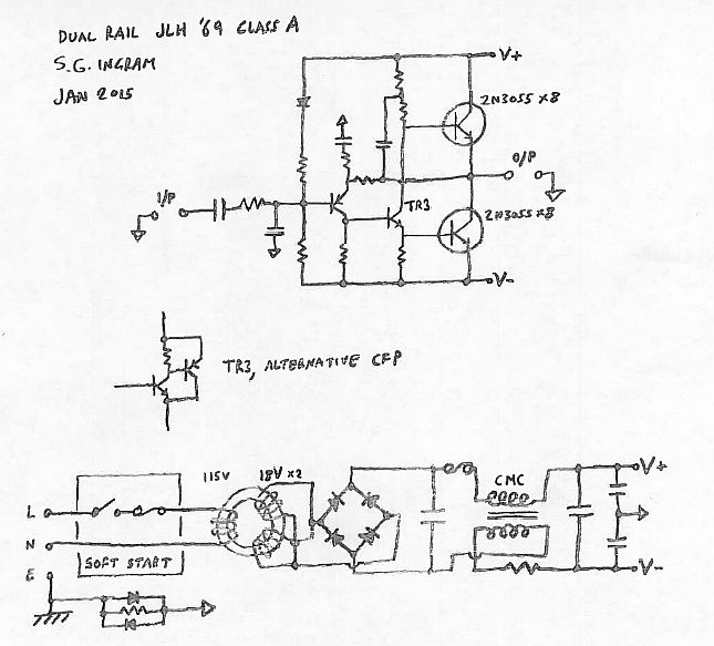
I think the schematic is incorrect (one secondary of the transformer is being shorted out? how does the ground current flow back through the transformer?) but I think for how it is intended to be the core will actually be subject to saturation from powersupply current. Fortunately in that application its not really the end of the world if it does saturate.
A CMC is just resistive (because of the winding resistance) to differential mode current because the fields cancel and there is no mutual inductance. For common mode currents the fields are in phase, so you see both inductances and also coupling between the windings like a transformer. Effectively it 'shorts out' high frequency common mode signals that appear at the input.
Swapping the phase of a winding just turns a CMC into a DMC (differential mode choke...). The behaviour for CM and DM signals is just swapped around. Effectively in the powersupply above it will be providing filtering of ripple generated by the rectification process and will be useless against filtering common-mode noise. Normally a CMC will do nothing to address rectification ripple but filters out common-mode noise such as high frequency interference which has been equally coupled in to the supply rail and ground.
To use a CMC as a single inductor you want to reverse the phase of one winding and then either wire them in series to get additive inductance but also additive winding resistance, or parallel for half the inductance and half the winding resistance.
The problem with using a CMC in a speaker crossover is that the current rating is usually determined by the gauge of the wire used on the windings and not the saturation current of the cores. In the intended usage of a CMC, only common-mode signals can cause the core to saturate, and the common-mode current is normally very low (<20mA) so the core can be small. They also tend to use high permeability cores to get the maximum amount of inductance in the smallest/cheapest package and high permeability cores typically saturate as lower current, size-for-size.
Last edited:
Member
Joined 2009
Paid Member
Unfortunately, there is no free-lunch. The common-mode choke, when used in differential mode (as I did) does not give the same inductance levels because you are not using the mutual-inductance (as noted, it is more the leakage inductance). In my case I was not concerned about this because of the use with high current charging spikes in a power supply - where even modest inductance provides a means to cut-off the high frequency hash from the rectifiers. The real benefit of the approach is that of low cost because common-mode chokes are cheap as chips whereas a purpose made dc-gapped choke is a more specialized item. I don't claim to have invented anything new by the way, I've seen something like this posted on the internet, I'll see if I can find a reference or two (attachments)..
J&K Audio Design (?)
Kanedaa pre-amp
I have no experience with cross-over design, but I had understood that hi-end design guru's like to avoid the use of magnetic cores on 'sound quality' grounds ? and the Royal Way is to use line-level cross-overs.
J&K Audio Design (?)
Kanedaa pre-amp
I have no experience with cross-over design, but I had understood that hi-end design guru's like to avoid the use of magnetic cores on 'sound quality' grounds ? and the Royal Way is to use line-level cross-overs.
Attachments

Last edited:
That is a jump, not a connection, it's a little difficult to make out.I think the schematic is incorrect (one secondary of the transformer is being shorted out?
Ah I see, so they are just wirinv the secondaries in parallel. There is still no return path for the output ground so it won't work properly as a dual supply. The "ground" is merely a virtual ground generated by a capacitor divider.That is a jump, not a connection, it's a little difficult to make out.
Sent from my Nexus 5 using Tapatalk
- Status
- Not open for further replies.
- Home
- Loudspeakers
- Multi-Way
- Use of "Common Mode" Chokes in crossovers