First off not an engineer, but I have adjusted bias of a couple of vintage amps with the help of a service manual that pretty much tells me where to stick my probes on the amp.
I do not have a service manual of my amp and emails to Usher has not yielded any results.
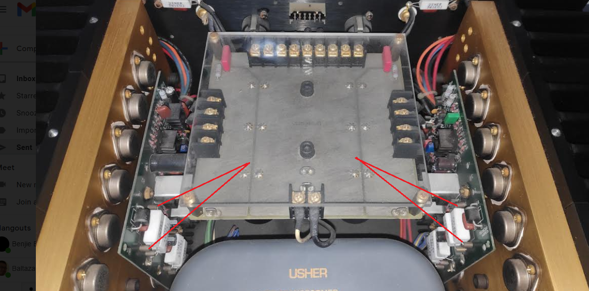
I know where the bias trimpots are, it is the blue trim pots on the left and right board. So if anyone can tell me where to exactly stick the negative and positive probe on my multimeter on the board, then that would be great.
Since there is only 1 set of trimpots, how is DC offset adjusted ?
Thanks
I do not have a service manual of my amp and emails to Usher has not yielded any results.
I know where the bias trimpots are, it is the blue trim pots on the left and right board. So if anyone can tell me where to exactly stick the negative and positive probe on my multimeter on the board, then that would be great.
Since there is only 1 set of trimpots, how is DC offset adjusted ?
Thanks
Attachments

Measure the voltage across one of the white rectangular emitter resistors.
But check their resistances first, and replace any bad ones.
You have to know the recommended current per device to adjust the bias.
Or you could just adjust the bias for a steady state heat sink temperature of ~50C,
since this is a class A amplifier. Do that over a period of several hours of continuous operation.
Last edited:
The amp is supposed to be 50 watts class A or 150 Class AB.
Is this correct ?
I read on another thread that the bias should be at 50ma and the heat sinks should be at a toasty 50 degrees c to get 50 watts Class A, same temp as what you suggested.
Right now after 1 hour warm up, the amp is at 36 degrees, after a serious workout with an Alon IV, 87dB, 3 ohms at 70hz, the heatsinks are at 41 degrees C.
I may not go full tilt right away, I might increase the bias to make the heat sinks idle at 40 degrees. If the sound improves to my liking, I may stay at this temp.
Is there a table where I can set the heat sink temp to a certain watts in Class A? Say at 50 watts class A. Heat sinks is at 50c. At 30 watts Class A, heat sinks is at 40c
Attachments

You'd need to know the heat sink details to estimate the power dissipated to reach 50C.
Just adjust for any heat sink temperature you want that is no more than that.
You could measure the power drawn from the AC line instead, deducting around 10%
for the transformer loss. I would still verify that the emitter resistors are all within tolerance.
Just adjust for any heat sink temperature you want that is no more than that.
You could measure the power drawn from the AC line instead, deducting around 10%
for the transformer loss. I would still verify that the emitter resistors are all within tolerance.
Last edited:
Yes, for measuring the resistance with the power off.
If measuring the voltage drop with the power on, be extremely careful not to short anything.
One slip will destroy the amp. Recommend for this case that secure clip leads be used,
attached when the amplifier is off, and left on for the entire time that it is powered.
If measuring the voltage drop with the power on, be extremely careful not to short anything.
One slip will destroy the amp. Recommend for this case that secure clip leads be used,
attached when the amplifier is off, and left on for the entire time that it is powered.
Yes, then V/R will tell you how much current is flowing in that transistor, but you don't know the mfr spec for that.
After adjusting, always verify the long-term heat sink temperature over several hours, to reach thermal equilibrium.
Never over 50C.
After adjusting, always verify the long-term heat sink temperature over several hours, to reach thermal equilibrium.
Never over 50C.
Heat sink temp will go down a bit when passing a signal, if played rather loudly for long enough.
If your room is warm (over 25C), the bias will have to be lowered to keep the sinks under 50C.
If your room is warm (over 25C), the bias will have to be lowered to keep the sinks under 50C.
Last edited:
Unfortunately my DMM is not working 🙁 lucky me. Will the amp operate if their open ? The amp sounds very good as it is right now.

Last edited:
I measured bias across the top most resistor and I am not getting anything??? DMM is set to 200m, tried 2, still nothing
I set my DMM wrong on the bias measurements 🙂
DMM on 20 amps setting as the 200m was not getting anything, Left channel 0.04 and Right channel is 0.03, so that would be 40ma and 30ma
DMM on 20 amps setting as the 200m was not getting anything, Left channel 0.04 and Right channel is 0.03, so that would be 40ma and 30ma
No, use a voltage setting on the DVM, not current. Best setting would be 200mV full scale.
You cannot measure current unless the DVM is connected in series with the resistor. Don't attempt to do that.
Remember never to short anything, or the amp will be toast.
You cannot measure current unless the DVM is connected in series with the resistor. Don't attempt to do that.
Remember never to short anything, or the amp will be toast.
- Home
- Amplifiers
- Solid State
- Usher R1.5 DC offset and Bias adjustment