Hi all, thanks for looking,
Basically, I have been building guitar distortion circuits and its been said that the effective gain with a simple transistor 2n3904 etc is about 40. So I have been reading about darlington pairs about getting more gain. As far as I can tell, I should be able to get increased gain with a darlington pair or similar. Simulations do not demonstrate this, but I would suspect that a darlington pair would give more gain. I simulated a simple electra type distortion with a simple sinlge 2n3904 transistor and a darlington pair with 2 2n3904s. Simulations do not show an increased gain. Is this configuration or similar (Sziklai pair) useful in this situation? Simulations actually show an increased gain with a single transistor vs. the darlington configuration, but it seems self -evident that a single 2n3904 will not give a gain of 85 but rather around 40. Does anyone have practical experience they can comment on about this idea of using a darlington pair for increased gain?
Basically, I have been building guitar distortion circuits and its been said that the effective gain with a simple transistor 2n3904 etc is about 40. So I have been reading about darlington pairs about getting more gain. As far as I can tell, I should be able to get increased gain with a darlington pair or similar. Simulations do not demonstrate this, but I would suspect that a darlington pair would give more gain. I simulated a simple electra type distortion with a simple sinlge 2n3904 transistor and a darlington pair with 2 2n3904s. Simulations do not show an increased gain. Is this configuration or similar (Sziklai pair) useful in this situation? Simulations actually show an increased gain with a single transistor vs. the darlington configuration, but it seems self -evident that a single 2n3904 will not give a gain of 85 but rather around 40. Does anyone have practical experience they can comment on about this idea of using a darlington pair for increased gain?
Does anyone have practical experience they can comment on about this idea of using
a darlington pair for increased gain?[/COLOR]
Darlingtons have higher beta (current gain), but most circuitry is designed to be insensitive to beta.
This is because the current gain is highly variable with operating conditions as well as unit-to-unit,
and is a poor design parameter. Instead voltage gain is needed in most cases, except for typical
power amplifier output stages. A Darlington would however likely load the preceding stage less,
which could result in somewhat higher gain and/or bandwidth.
The output clamping diodes limit the voltage output in any case. You could use two diodes in series
for each polarity, instead of just one. That would give you twice the output, +/-1.2V instead of +/- 0.6V.
Last edited:
darlington pair gain for preamp
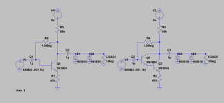
Sure, here is a simple example. The gain theoretically should be 150 about based on the the collector to emitter resistor ratio, but I'm told that gain is limited to about 40 etc practically., simulations though show 85 for the circuit on the left and 60 for circuit on the right (darlington config). I was just trying to get a gain of about 100 or so with an extra transistor.
Sure, here is a simple example. The gain theoretically should be 150 about based on the the collector to emitter resistor ratio, but I'm told that gain is limited to about 40 etc practically., simulations though show 85 for the circuit on the left and 60 for circuit on the right (darlington config). I was just trying to get a gain of about 100 or so with an extra transistor.
Attachments
Details of what you are trying to do would be helpful.
The gain is the trivial part of a distortion circuit. The valuable part is where in the circuit clipping occurs and the sonic characteristics this imparts.
There are examples where Darlingtons are used, typically something like a 2 transistor distortion circuit, and keeps part counts low.
The gain is the trivial part of a distortion circuit. The valuable part is where in the circuit clipping occurs and the sonic characteristics this imparts.
There are examples where Darlingtons are used, typically something like a 2 transistor distortion circuit, and keeps part counts low.
Sure, here is a simple example. The gain theoretically should be 150 about based on the the collector to emitter
resistor ratio, but I'm told that gain is limited to about 40 etc practically., simulations though show 85 for the circuit on the left and 60 for circuit on the right (darlington config). I was just trying to get a gain of about 100 or so with an extra transistor.
The voltage gain being equal to the ratio of the collector resistor to the emitter resistor is a rough rule of thumb.
What input level are you using? The output is limited to 0.6V peak regardless, so the voltage gain would be higher
if you reduce the input signal level to the point where it just clips. Or, use two series diodes in each location
if you really do need a higher absolute output voltage when clipping.
Last edited:
Well, here was my thinking, I made the circuit on the left and I increased the collector resistor from 0 up to about 20k and above 20k there is no audible change I can hear. Turns out that is about a gain of 40 theoretically, and I am told that is about the limit of a simple single transistor (2n3904). So my thinking was if I made a darlington pair maybe I could get more gain out of the circuit.

Turns out that is about a gain of 40 theoretically, and I am told that is about the limit
of a simple single transistor (2n3904). So my thinking was if I made a darlington pair
maybe I could get more gain out of the circuit.
By gain, you mean output voltage for a constant input?
You can't get more than 0.6V out of that circuit, and even less for Schottky diodes.
Of course, if you clip harder with a higher input, it will sound somewhat louder.
Last edited:
Well, I know that maximum voltage and minimum voltage are going to be limited by the clipping diodes, but if you drive the diodes with a higher and higher voltage, you should get more of a square wave as the output and the "gain" or "drive" increases. For example, if you took an op amp with a voltage gain of 40 and 200 and the output is clipped by output diodes, you would expect the same maximum and minimum voltages clipping on the diodes, but the waveform would be more square with the op amp with gain of 200. I'm trying to drive the diodes harder to get more of a square wave. That's what I was hoping to do. I've read the "gain" of guitar distortion circuits are around 150 or so. But really that is not really "gain" because that would be the output/input voltage. What I think they refer to in guitar distortion circuits is "gain" before clippling or "gain" driving clipping. Maybe gain is not even the right word. But, I guess it would make sense to call it gain if the input voltage is say 1mv amplitude, and then the circuit produces a sine wave amplitude 150mv, but clips at about 300mv peak.
I'm trying to drive the diodes harder to get more of a square wave.
A simple high gain op amp circuit could do much better at clipping, if you don't need a lot of adjustment.
No diodes required.
Last edited:
The Voltage Gain of a single BJT "can" be a Thousand+.
But that requires super-low input impedance (sucks your guitar) and super-high output impedance (any load sucks it).
In "iterative" design the limit is hFE, though usually less due to bias networks.
Darlington is 2 transistors. (Yes, you can buy them as one device.)
The same two (separate) transistors can be rigged one after the other. Gains tend to multiply. 40*40 would be 1,600!! Which means you will drown in idle hiss and have to cut-back somehow (easily done).
Even at gain of 40, "Miller Effect" through the 1.5Meg resistor is significantly reducing your input impedance. 1.5Meg/40 is 37K, a very low value for guitar which runs 5K in bass/mid but 200K in treble. We often see this in older fuzz effects. It reduces the highs going into the fuzz (by loading the pickup inductance). If you clip high-highs you get a hash of a-harmonic IM products. Sounds annoying (even by fuzz standards). And we don't need more highs, clipping the bass/mids makes plenty of highs. So this works to tame the bandwidth when you come right off a guitar (and interactive with axe Vol pot) but works very different after any sort of buffer.
There are forums where the denizens have build thousands of variants of the basic dozen fuzzes plus dozens of further-out new ideas. I think you would find more experience and practical know-how if you found one of those forums.
I'm trying to drive the diodes harder to get more of a square wave. That's what I was hoping to do.
Here's an example of what you can do with an op amp instead. It automatically does what you want.
The diodes D1 and D2 are Zener diodes (which act like regular diodes in the reverse direction).
A similar circuit can be designed for single supply operation.
http://www.circuitstoday.com/wp-content/uploads/2011/06/Op-Amp-comparator-circuit.jpg
Last edited:
Thanks for the great explanation PRR. I am going to check out some pedal stompbox forums put of curiosity. When i get home ill try tinkering a bit with these circuits if i find anything interesting i will post. Thanks rayma for the link. I think i saw a circuit like that crate guitar amplifiers used.
Changing a simple BJT circuit from a single transistor to a Darlington will, as the OP has discovered, reduce voltage gain. I don't know why he expected anything different. All the Darlington will do is raise input impedance, which may or may not be relevant. It certainly won't be relevant in a simulation driven from an AC voltage source (with presumably zero output impedance) - this is almost certainly a poor model for the real circuit. In any case, the increase in input impedance due to the increased current gain may be swamped by the feedback from collector to base via the resistor.
A BJT is a transconductance amplifier with finite input and output impedances. Input impedance is set mainly by current gain. Output impedance is set mainly by Early effect. Together these limit voltage gain. Circuit details then reduce it further.
A BJT is a transconductance amplifier with finite input and output impedances. Input impedance is set mainly by current gain. Output impedance is set mainly by Early effect. Together these limit voltage gain. Circuit details then reduce it further.
Thanks for the reply. I know that replacing a transistor with a darlington will reduce the voltage gain a little. But Ive also been told a simple bipolar transistor can only achieve a gain of about 40 or so using it in a class a configuration. So my question is, which can achieve higher voltage gain a) a single class a bjt amp with collector to emitter ratio of say 150, or b) a darlington configuration with a collector to emitter ratio of 150.
We have already established that a Darlington has lower voltage gain than a single BJT. Why ask the same question again?
Ok Gary, what you want to do is make two of the circuits in post #8 to play with. For the first stage, substitute your diode clippers for a potentiometer. Feed the wiper of the pot into the second stage. Voila! Mucho voltage gain to experiment with. Now start playing with bias and feedback resistors to get rid of the way too much voltage gain.
If you were doing a radio antenna amplifier, these two stages might provide enough gain to tune in some AM stations with a single diode and an earphone. Depends on the antenna tuning circuit up front. For a guitar distortionator, these two stages could run a single-ended darlington power stage and drive a speaker. Do you understand?
If you were doing a radio antenna amplifier, these two stages might provide enough gain to tune in some AM stations with a single diode and an earphone. Depends on the antenna tuning circuit up front. For a guitar distortionator, these two stages could run a single-ended darlington power stage and drive a speaker. Do you understand?
Thanks jeff5may. I was experimenting with a couple stages similar to what you were saying, and I think I got a decent sounding distortion. I kept the diode clippers on the first stage and put a potentiometer between the first and second stage, and then lowered the wiper to get rid of some of the noise, then, I replaced it with a voltage divider. The second stage was ran into another distortion stage with diodes in the feedback loop. I then ran it into a scaled down marshall tonestack and I think it sounds pretty good for an experiment. I'm going to try some different clipping variations and leaving out the first set of diodes and just a voltage divider. Thanks everyone
Attachments

I cut out the middle diodes and then ran the first stage into the second, but added Red LEDs as feedback clipping on the second stage for higer output levels. After running through the tonestack as shown, I got peak values of 1.4v measured, which I suppose is around 1 volt rms roughly. (I thought about adding some Infrared LEDs that clip at around 1v at the very end to clip of the tall peaks if this is an issue going into a power amp but have not done this).
Attachments

- Status
- Not open for further replies.
- Home
- Live Sound
- Instruments and Amps
- using darlington configuration for increase gain in guitar distortion circuit