Over the years many tube circuits caught my eye and challenged my ability to understand and sure enough I came to understand how Triodes worked but not Pentodes.
So taking my knowledge of modern electronics, Jfets, Mosfets, Transistors, IC's etc. I decided to think about Triodes and what property does a Triode have that no other modern devices have. One thing stood out - the Grid, Grid resistance can be very high when negatively biased relative to the Cathode, also its capacitance can be very low typically 1-2pF (this remains true if gain is kept low). OK so you say that a Jfet can do this but a Triode Grid can be very robust as regards large over voltages and typically if a Triode fails it goes open circuit whereas a Jfet can easily go short circuit.
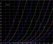
Now I was thinking that it would be interesting to build a Triode front end with very high Grid resistance and low gain (say about x3) to keep the Miller effect down. With a Grid capacitance of say 1.5pF I could be looking at no more than about 6pF effective Grid input capacitance. I bought some GE (or Chinese copy) JAN 5670W tubes these have much the same specifications as 5670 2C51 6385 396A etc. This is a small Dual Triode that can dissipate (Anode dissipation) about 1.35Watts per Triode maximum. Here is a graph of its Anode voltage vs current for different grid voltages:

Next question is bias, where do I want the DC bias point to be on this graph? After some thought I came up with the following thinking:
Hence the "sweet spot" at Anode current of 8mA and Anode voltage of 130 Volts (a DC bias dissipation in the tube of about 1 Watt).
Having tested my JAN 5670W Dual Triodes (and I had bought a lot of them) I knew that for a fixed Anode current and Anode voltage the Grid voltage varied quite a lot around that -1 Volt to -2 Volt range. So then came the "eureka" moment, I realised that I needed a circuit that did the following:-
Another "eureka" moment and I realised that I was throwing away all the Triode front end preamp circuitry I had ever seen over many many years - never to touch it or go near it again because it never set both DC bias current and DC bias Anode voltage and made them both fixed and constant. So now I had a circuit that was very tolerant of quite large specification differences between Triodes and even between different types of Triodes. Here is the circuit in its simplest form:

The 6K Anode load resistor used has a constant current flowing through it so it fixes the Anode bias voltage. It does this by Ohms law - voltage across the 6K Anode resistor is 8mA x 6K that's 48 volts. So the Anode voltage stays at the HT supply voltage of 180 Volts minus the 48 volts which is 132 Volts. So you have a fixed Anode to Cathode current because of the 8mA current sink and a fixed Anode DC bias voltage. The advantage of this is fixing two axes of the characteristic curves for this Triode at the good place (the sweet spot). Obviously for AC signals then of course the current from Anode to Cathode and the Anode voltage are varying around the DC bias values.
So taking my knowledge of modern electronics, Jfets, Mosfets, Transistors, IC's etc. I decided to think about Triodes and what property does a Triode have that no other modern devices have. One thing stood out - the Grid, Grid resistance can be very high when negatively biased relative to the Cathode, also its capacitance can be very low typically 1-2pF (this remains true if gain is kept low). OK so you say that a Jfet can do this but a Triode Grid can be very robust as regards large over voltages and typically if a Triode fails it goes open circuit whereas a Jfet can easily go short circuit.
Now I was thinking that it would be interesting to build a Triode front end with very high Grid resistance and low gain (say about x3) to keep the Miller effect down. With a Grid capacitance of say 1.5pF I could be looking at no more than about 6pF effective Grid input capacitance. I bought some GE (or Chinese copy) JAN 5670W tubes these have much the same specifications as 5670 2C51 6385 396A etc. This is a small Dual Triode that can dissipate (Anode dissipation) about 1.35Watts per Triode maximum. Here is a graph of its Anode voltage vs current for different grid voltages:
Next question is bias, where do I want the DC bias point to be on this graph? After some thought I came up with the following thinking:
- DC bias dissipation must be lower than the tube's maximum so about 1 Watt seemed OK
- DC bias dissipation should not be too low (small currents increase noise)
- The DC bias sweet spot needed to be in a place that looked most linear (Grid voltage curves evenly spaced and as straight as they get)
- The DC bias sweet spot should be nowhere near positive Grid voltages (relative to the Cathode)
Hence the "sweet spot" at Anode current of 8mA and Anode voltage of 130 Volts (a DC bias dissipation in the tube of about 1 Watt).
Having tested my JAN 5670W Dual Triodes (and I had bought a lot of them) I knew that for a fixed Anode current and Anode voltage the Grid voltage varied quite a lot around that -1 Volt to -2 Volt range. So then came the "eureka" moment, I realised that I needed a circuit that did the following:-
- Kept the DC bias current flowing from Anode to Cathode at always 8mA (the final circuit was about 8.15mA)
- Kept the DC bias Anode voltage at always 130 Volts
- Allowed the DC bias Grid to Cathode voltage to vary quite a lot to keep the above true
- Set the Gain to x3 and give me plenty of negative feedback local to the Triode to reduce distortion and keep Miller effect Grid capacitance low
Another "eureka" moment and I realised that I was throwing away all the Triode front end preamp circuitry I had ever seen over many many years - never to touch it or go near it again because it never set both DC bias current and DC bias Anode voltage and made them both fixed and constant. So now I had a circuit that was very tolerant of quite large specification differences between Triodes and even between different types of Triodes. Here is the circuit in its simplest form:
The 6K Anode load resistor used has a constant current flowing through it so it fixes the Anode bias voltage. It does this by Ohms law - voltage across the 6K Anode resistor is 8mA x 6K that's 48 volts. So the Anode voltage stays at the HT supply voltage of 180 Volts minus the 48 volts which is 132 Volts. So you have a fixed Anode to Cathode current because of the 8mA current sink and a fixed Anode DC bias voltage. The advantage of this is fixing two axes of the characteristic curves for this Triode at the good place (the sweet spot). Obviously for AC signals then of course the current from Anode to Cathode and the Anode voltage are varying around the DC bias values.
Last edited:
Here is a LTspice simulation circuit I used to test what was happening:

Here is the very simplified LTSpice model I used for the 5670 Triode (I tested the model and compared it against datasheet characteristic curves and its very close as long as the Grid voltage relative to Cathode is always less than zero, is always negative):
.subckt 5670 A G K params: mu=40.9 ex=1.71 kg1=825 kp=126 kvb=708
*Quiescent current
e1 7 0 value= {v(A,K)/kp*log(1+exp(kp*(1/mu+v(G,K)/sqrt(kvb+v(A,K)*v(A,K)))))}
*Voltage dependence
g1 A K value= {(pwr(v(7),ex)+pwrs(v(7),ex))/kg1}
.ends
-
I then went ahead and designed a prototype Stereo Valve Headphone Preamp. The circuit is in two parts, the preamp and the power supplies. If you are tempted to build this be aware that the mains transformer needs fuses etc for safety and with tube/valve circuitry always be aware of the dangers of high voltage DC power supply lines. Work safely.
Here are the circuits. Note that U1 should be a suitable high quality Opamp capable of driving headphones. You may need larger decoupling capacitors to remove mains hum on the 180 Volt HT line. Add an input 1u decoupling capacitor to InL and InR if your input is not decoupled elsewhere:


-
Here are the circuits. Note that U1 should be a suitable high quality Opamp capable of driving headphones. You may need larger decoupling capacitors to remove mains hum on the 180 Volt HT line. Add an input 1u decoupling capacitor to InL and InR if your input is not decoupled elsewhere:
-
Last edited:
Grid resistance is high but no infinite. Grid leak resistance has a maximum indicated in the data sheets by the manufacturer.
There are two grid currents: a positive and a negative. Positive current is mainly beacuse of residual gas(es) inside the glass. Gas is ionized and ions and electrons may flow from grid to anode without any control externally. If very serious, it finishes with thermal runaway and tube destroyed. Mainly it happens in larger tubes.
Negative current is there 'cos some electrons traveling from cathode to anode strikes grid wires or mesh and rods, and return externaly though grid leak. The former increases tube bias to positive and latter to negative. Open grid return equals both.
So take rhe data sheet as a serious limit.

The concept of a "Grid leak" resistance is unhelpful as regards how this circuit and method of bias works. The constant current generator will adjust the DC bias potential between Grid and Cathode in such a way as to keep the DC bias Anode to Cathode current at exactly 8.192mA. Even if the current through the 620K input resistor shown above was enough to shift the Grid DC level by 1 or 2 Volts positive or negative the constant current generator will adjust to cancel it out.Grid resistance is high but no infinite. Grid leak resistance has a maximum indicated in the data sheets by the manufacturer.
When tubes are manufactured vacuum pumps such as the Diffusion Vacuum Pump are used to remove air from inside the tube, then the tube is sealed, then a "getter" inside the tube is heated to red hot by HF heating to scrape up remaining air. For small low power Triodes like the 5670 this process can be very very effective.
The constant current generator used by this circuit will always keep the Grid DC level negative relative to the Cathode and electrons are therefore mainly repelled by the Grid wires.
I have studied many tube datasheets from the past and they do not describe well how the tube works when they are compared with modern discrete semiconductor datasheets. The concept of "Grid leak resistor" would be a typical example. Written in today's world a tube datasheet would give information about Grid leakage current and quote this as a figure.
Not sure. The 620K resistor is effectively a grid leakage and DC return to cathode.
In my circuit consider the voltage at VkL (or VkR). At AC voltage AC is shorted to 0V by the 100u capacitor but at DC the voltage VkL relative to 0V is changing over time as needed (because of Grid leakage current, different tube characteristics etc) to exactly maintain a constant DC bias current of 8.192mA from Anode to Cathode. This bias current is a certainty because that's what Opamp U2 is doing and it responds very fast.
To give you an arithmetic example lets say that the Cathode needs to be 2 Volts more positive than the Grid for exactly the 8.192mA DC bias current to flow and lets assume that the Grid DC level is 0V (Grid leakage current assumed to be zero). So that means that the voltage across the 1K5 Cathode resistor is by Ohms law 8.192mA x 1K5 and that's 12.288 Volts so the voltage VkL is -12.288 -2 which is -10.288 Volts. So in this example the Voltage VkL is negative of 0V and is -10.288 Volts. VkL (and VkR) will constantly adapt to keep the DC bias current between Anode and Cathode at exactly 8.192mA. If the Grid leakage current is not zero it will cause a DC voltage across the 620K Grid resistor which will be cancelled out by a small change in VkL (or VkR).
The 620K Grid resistor can be changed or even left out it all depends what's feeding the preamp input. Ideally (and usually the case) we would like to feed the preamp input from a low impedance DC coupled input, then you can leave out the 620K resistor. If you want to use this circuit for input from a very high impedance low bandwidth transducer input then you can make this Grid resistor a lot larger depending upon the tube's Grid leakage current.
As regards Langford Smith and Waldman books and other publications, do you have any examples of an existing circuit that sets Triode DC bias such that the DC operating point is always in the same place for DC Anode current and DC Anode voltage please? Can you post a diagram maybe?
To try to explain this in a different way - At steady state the power dissipated in the valve due to this bias is approximately 8mA x 130V, about 1Watt. In this example the Grid DC level pin 3 is 0V zero volts, the Cathode pin 2 stays at about between +1 and +2 volts. So the Grid bias is negative of the Cathode as it needs to be. The V-15 supply is needed to give the current generator enough headroom. The 1K5 Cathode resistor provides negative feedback helping to keep distortion low. At the gain of approximately x3 the THD can be as good as -60bB for this circuit assuming a 1 volt peak input signal. The Grid input impedance can of course be very high.
Also ran the simulation for two Triodes in a Cascade configuration, advantage being less Grid to Anode capacitance, disadvantage being increased B+ HT voltages:

Also ran the simulation for two Triodes in a Cascade configuration, advantage being less Grid to Anode capacitance, disadvantage being increased B+ HT voltages:
With regard to the "sweet spot" this kind of bias is aiming at, I tried plotting the same graph adding a load line for the 6K Anode resistor shown, here is that graph:

To my way of thinking the middle useful part of this load line is in the most linear part of the characteristic curve and is held there by the constant current bias.
To my way of thinking the middle useful part of this load line is in the most linear part of the characteristic curve and is held there by the constant current bias.
DC 'sweet spot' also depends on the load and the valve/tube you are working with.
BTW - Looking at your chosen plate curve, I see you are losing a lot of gain. Clearly with such a low plate load, you don't want to get into the 'knees' which will happen really fast if you bias further negative for your 5670.
Some valves/tubes are really linear across a wider range. Some are just nasty to try and deal with as Triodes. Some pentodes are astonishingly linear, while not linear at all when triode strapped. That's part of the fun in this hobby.
DC 'sweet spot' also depends on the load and the valve/tube you are working with.
Well yes but we are looking at the characteristic curve for this valve type. Also you will see the full circuit diagram in post #3, the intention is to feed the Anode output into an Opamp and the LTspice simulation has the same load as that circuit ie Anode via a 4u7 capacitor with 100K resistor to 0V.
BTW - Looking at your chosen plate curve, I see you are losing a lot of gain. Clearly with such a low plate load, you don't want to get into the 'knees' which will happen really fast if you bias further negative for your 5670.
Not loosing a lot of gain.
The gain is deliberately being traded for negative feedback, at the tube, which greatly reduces Total Harmonic Distortion. Referring to the simulation circuit in post #2 as the Grid of U1 goes positive the Anode voltage drops but also the Cathode voltage increases to a lesser extent (because of the same current through R4 and R3) so there is negative feedback and that is dropping the gain to x3.
Further negative bias can't happen because the constant current bias and the 6K R4 always forces and keeps the DC bias at the "sweet spot" It would be there if the tube characteristics changed or even if you fitted a different tube type (within reason) the DC bias "sweet spot" can't move from 8mA at 130 Volts. The load line as drawn can't move, all that can move are the Grid voltage curves.
Yes pentodes are much more linear but much more complicated build and to use also. The challenge is understanding what's going on and for me using modern solid state devices to support the Triode.
Thanks for having a look at it.
- Home
- Amplifiers
- Tubes / Valves
- Vacuum Tube bias for designers