Too simple?
I came across this very simple HV shunt regulator at tubecad.com. It could easily fit on a 50mm x 80mm pcb and bolted flat to a 50x80x12mm flat heatsink when you want to regulate each channel separately in a smallish chassis. Is this circuit "too simple"? I like simple. My application is to regulate B+ for approx 20 to 25 MA at 350 volts.
link https://tubecad.com/2007/07/blog0115.htm
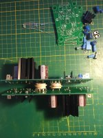
Attachments

Last edited:
Yes its scarce now, I bought 10 of them about 4 months ago still unused, now I see they are all backordered! Supply chains are truly in bad shape. A transformer cover set I ordered from China a year ago cost $5 to ship, now I see that same cover pair with a shipping rate of $23, and the covers are only $12 a pair.
Back to the circuit... I'm a Newby hobbyist but trying to understand how this works. I see the gate of the 840 trapped in a virtual center tap of the ripple between the 1M-1M divider. That drives the 840 in opposition to the ripple? Is that the basis of it?
On the unavailability of 10M45S... Is there a substitute?
On the unavailability of 10M45S... Is there a substitute?
Are you convinced that you MUST use a depletion mode MOSFET? Take a quick glance at this all-enhancement-mode version. Is there anything wrong with it? Why won't it work equally well? It sure does eliminate the very hard to buy 10M45S. But is it fatally flawed?
R1 and R2 are the same two resistors as in the TubeCad circuit, with the same not-quite-unity resistance ratio. Cff is the same feedforward capacitor as in the TubeCad circuit.
M1 and M2 are enhancement mode MOSFETs, chosen for their voltage rating and for their excessively conservative Safe Operating Area plots on the datasheet.
RV9 is a 15-turn trimmer potentiometer. It adjusts the current flowing in the shunt section (the MOSFETs). Connect a digital voltmeter across resistor R2 -- thanks to Ohm's Law we know that V(R2) = M1_current * R2. Algebra conculdes: M1_current = V(R2) / R2. So we dial RV9 up and down until we get the value of M1 current that we desire. Sweet!
"PROT" are gate-to-source protection networks which prevent gate oxide rupture in the two MOSFETs. Put them in if you think you need them, or if you think the risk-versus-reward of having them, exceeds the risk-versus-reward of NOT having them. It's okay to make a different choice than John Broskie made. It's also okay to make the same choice. Your call, your responsibility.
It's also okay to draw the circuit with the input on the left and the output on the right. That's a choice I made.
_
Attachments

Well THAT'S embarrassing. I assumed the IXCP-10M45S was a depletion mode MOSFET but that's wrong. Terribly wrong. And so is post #5. Please ignore it. Better yet, have a moderator delete post #5, lest it confuse someone in the future.
I apologize for the careless error.
I apologize for the careless error.
Thanks Mark,
No problem! I was just responding to maybe get some part values nailed down for your post so I could head down to my bench. Since the 10M45S is unobtanium. Maybe its time to come up with a HV shunt regulator that uses commonly available parts and can do it with under 10 parts as above! That would be so cool. I certainly can't do it, but using the John Broskie circuit as the framework, can it be done without 10M45S?
No problem! I was just responding to maybe get some part values nailed down for your post so I could head down to my bench. Since the 10M45S is unobtanium. Maybe its time to come up with a HV shunt regulator that uses commonly available parts and can do it with under 10 parts as above! That would be so cool. I certainly can't do it, but using the John Broskie circuit as the framework, can it be done without 10M45S?

The 400 V rating of the 47 uF capacitor in the schematic in post #1 must be a typo.
What's with the direction of current being opposite to the convential direction?
What's with the direction of current being opposite to the convential direction?
What's with the direction of current being opposite to the conventional direction?
I agree and totally unnecessary. And on the page he uses some drawings going the other way!
Low parts count is not what I optimize for; that's not how I roll.
Here's a shunt regulator design of mine that I've actually built and tested; it works great BUT there are 20 components, not 10. And it's a low voltage shunt regulator for solid state circuitry: +36VDC input, +29VDC regulated output. Still, if you can get some useful ideas out of it, please do! I'd be flattered. The circuit was part of the Ship Of Theseus project and its schematic + engineering discussion are attached to post #1 of the S.O.T. Forum thread (here)
And if you want to call C2 below a "feedforward capacitor", thus creating a feedforward shunt regulator, it won't hurt my feelings.
The CCS sources ( VbeQ1 / (R2 parallel R3) ) which is about 40 or 50 milliamps. The load takes what it wants and Q2 takes the rest. Q2, U1, R10, R11 form a negative feedback loop which regulates the output tightly.
_
Attachments

Last edited:
When I needed a cheap quick shunt, for 300V, I used 4 75V 5W zener diodes in series on a dropping resistor...Total cost under 1$. 🙂
Are not Zeners noisy?
Compared to the 120Hz they clip off? Nope.
Bypass them with a cap, of course... But it took away the noise in my case 🙂
I usually use VR tubes, but I needed more current.
These days, I use a series regulator based on TL783.
Bypass them with a cap, of course... But it took away the noise in my case 🙂
I usually use VR tubes, but I needed more current.
These days, I use a series regulator based on TL783.
I made a simple shunt regulator with an 6BQ5/EL84 once.
Works great, and is really low noise.
Works great, and is really low noise.
Attachments


Well THAT'S embarrassing. I assumed the IXCP-10M45S was a depletion mode MOSFET but that's wrong. Terribly wrong. And so is post #5. Please ignore it. Better yet, have a moderator delete post #5, lest it confuse someone in the future.
I apologize for the careless error.
10M45S is a depletion mode device (negative Vgs required). Check out the datasheet.
https://www.mouser.com/datasheet/2/205/98704-13273.pdf
This has been discussed before:
https://www.diyaudio.com/community/threads/replacement-for-10m45-ccs.221058/
As discussed in the thread above, one could use DN2540 instead.
IXCY-10M45S is the surface mount version.
IXCP-10M45S is the TO-220 version.
v4lve lover, thanks, in a future project I will do a tube shunt reg. But in this now case I'm looking to squeeze two small regulators to the inside side panels of a chassis with a small flat heatsining. So this small circuit looked like just the ticket.

While we're at suggesting shunt regulators... What about Morgan Jones' Statistical Regulator? It's simplicity itself. A CCS cascode pair of DN2540 in series (as current regulator) with a shunt zener string as the voltage stabilizer.
https://www.diyaudio.com/community/threads/statistical-regulator-from-va-4rd-edition.253577/
https://www.diyaudio.com/community/threads/statistical-regulator-from-va-4rd-edition.253577/
Attachments

Interesting regulator. Too bad all this is mute it looks like the DN2540 chip is also unobtanium. So many great regulators and CCS use these chips, Salas HV, etc.
Now I did see sellers in China at great prices but I really don't think you can trust many of the China sellers on eBay, I've heard of counterfeits. My son in law ordered a tool chest from an ebay China seller, he received a small plastic doll and a sucker note. Anyone know if the chips from China are legit for either of these dn2540 or 10m45s?
Now I did see sellers in China at great prices but I really don't think you can trust many of the China sellers on eBay, I've heard of counterfeits. My son in law ordered a tool chest from an ebay China seller, he received a small plastic doll and a sucker note. Anyone know if the chips from China are legit for either of these dn2540 or 10m45s?
I don't think so. (But John can be tricky.) I think the '840 is just soaking-up half the voltage and power because the 10M45S alone could not stand the stress.I see the gate of the 840 trapped in a virtual center tap of the ripple between the 1M-1M divider. That drives the 840 in opposition to the ripple? Is that the basis of it?
- Home
- Amplifiers
- Tubes / Valves
- Very low parts count shunt regulator