Hi,
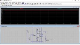
I am planning to build a virtual ground circuit as attached.
Now, the OpAmps that I have at hand are NE5534 and OP77. And I am really not sure, which one to prefer: The NE5534 is better at noise, the OP77 is better at bias current and PSRR/CMRR.
Can anybody give me a hint what the critical values are in this case? I really don't know 😢
Thank you!!
Attachments
My instincts say that given the 1uF filtering at the output that the opamp will make little difference. I'd even go as far as thinking a 741 would give similar overall results to something exotic.
Transient response might be more of a real and measurable difference which I suppose depends on what you are going to ultimately power with this.
Transient response might be more of a real and measurable difference which I suppose depends on what you are going to ultimately power with this.
That seems like a pretty easy sort of a load then and the circuit design looks fine at first glance
This is where transient response comes into play but your load is going to be essential constant so I don't really think you would have problems here. If the load was pulsing something at highish current then it might make a difference.
Noise is always interesting when talking power supplies and the problem is that no matter how quiet a supply is at a given point (such as across the 1uF caps) that can all get blown away a few centimetres further down a PCB track or a piece of wire. You will always see much more noise at the destination and that usually swamps any small gains made at the power supply or regulator.
(You can always socket the opamp and do measurements when its all working and see if differing opamps really do change anything)
P.S. Slew rate of the NE5534 is way better than that of the OP77.
This is where transient response comes into play but your load is going to be essential constant so I don't really think you would have problems here. If the load was pulsing something at highish current then it might make a difference.
Noise is always interesting when talking power supplies and the problem is that no matter how quiet a supply is at a given point (such as across the 1uF caps) that can all get blown away a few centimetres further down a PCB track or a piece of wire. You will always see much more noise at the destination and that usually swamps any small gains made at the power supply or regulator.
(You can always socket the opamp and do measurements when its all working and see if differing opamps really do change anything)
Thank you, again! Yes, the PCB is designed with a socket, and I will try. And maybe finally get some appropriate equipment (besides my ears) to do such kind of measurements....
I suppose it could well oscillate with a 5534 because they are not unity gain stable. The 5534 doesn't sound the best choice on a few levels really for something like this.
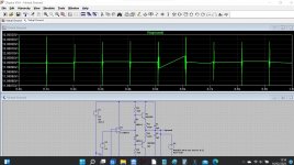
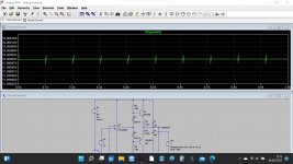
Also sharp pulses of significant current as a load probably would never occur in real life in your application. I set mine to have a rise and fall of 1 millisecond.
Also sharp pulses of significant current as a load probably would never occur in real life in your application. I set mine to have a rise and fall of 1 millisecond.
I have not met many op-amps that like having a heavy capacitive load on the output.I suppose it could well oscillate with a 5534 because they are not unity gain stable.
Note that negative feedback is taken around the entire loop, including the output transistors and the 1uF caps shorting the output to ground. This is a recipe for poor loop stability, or outright instability.
In this case, it's not just the op-amp's own phase margin we have to worry about. There is additional phase lag from the buffer transistors, eating up phase margin and pushing the circuit further towards instability. Then the capacitors at the output add even more phase lag, torturing the poor op-amp even more. Finally you have heavy NFB (100%, for unity gain) from the output all the way back to the input.
To me, the entire circuit looks like an exercise in how not to use an op-amp. 🙁
The little rail-splitter IC is cute, though. I hadn't heard of it before, and it sounds like a useful trick to have up one's sleeve. From the TI TLE2426 datasheet, output impedance is very low (nominally 7.5 milliohms), and it works very well by itself.
To tell the truth, adding the op-amp and buffer transistors only worsens stability, while adding cost, eating up board space, and adding complexity. Unless you need to source or sink much more current than the TLE2426 can handle on its own, I think you're much better off using just the IC by itself, the way the TI designers intended it to be used.
-Gnobuddy
1. If you are going to use an op-amp and buffer, what point is there using a LTE2426???
2. The passive decoupling caps need to be able to take over at whatever frequency the op-amp becomes too slow.
3. You do not need Rail-rail output. You want DC output. And you need to current limit the buffer so that it cannot be destroyed.
4. Better to just set the virtual ground with the amplifier(s), ie the input ground DC reference is a simple divider, and the output ground is a couple caps to either rail, that will follow the DC from the amp output. This means using the virtual ground as a voltage reference only and not as a current source.
5. If you must use a common virtual ground, just the buffer stage in Mooly's circuit is optimal, with no op-amp, no 12V reference. The buffer has a built-in divider being the two bias resistors and it will sink more current than the transistors can safely handle. If you want a lower dynamic impedance, use bigger caps.
PS: if you insist on using an op-amp, feedback should be taken before a build-out RL to the virtual ground. This prevents the stability problems.
Last edited:
Just the TLE2426 is all you need. If you're concerned about noise, get the DIP version and use the Noise Reduction pin, as per the datasheet. Also pay attention to Figure 17.Actually, it's intended for the line output stage of a DAC, nothing more than a couple of opamps, caps, and resistors.
What's wrong with a couple thousand microFarads?
MUCH quieter and more stable than any chip. (Your push-pull emitter followers may add crossover distortion.)
You do need some DC split, and this can be tricky, if audio path bootstraps its own input error. But not knowing the rest of your plan I don't know what to say.
MUCH quieter and more stable than any chip. (Your push-pull emitter followers may add crossover distortion.)
You do need some DC split, and this can be tricky, if audio path bootstraps its own input error. But not knowing the rest of your plan I don't know what to say.
True enough but the basic circuit could certainly be made to work. Whether its the best approach is open to debate...I have not met many op-amps that like having a heavy capacitive load on the output.
Note that negative feedback is taken around the entire loop, including the output transistors and the 1uF caps
Thanks to all of you for your great contributions! 
When collecting information of potential circuits, I found most of the possibilities discussed on
Tangentsoft and
head-fi.org (there are even PCBs available on Goldpoint).
Actually, there is just a few "soft" reasons why I decided to build this special circuit:

When collecting information of potential circuits, I found most of the possibilities discussed on
Tangentsoft and
head-fi.org (there are even PCBs available on Goldpoint).
Actually, there is just a few "soft" reasons why I decided to build this special circuit:
- I am a hobbyist and I want to learn something (and your answers helped a lot)
- I get 5 PCBs instead of only one. So I wanted a solution which can source/sink some more current to be more flexible for other use cases (which has disadvantages, I know)
- Hey, we are on diyaudio - the circuit has an NE5534 and an AB buffer stage. What else do you need? 😉
Best practice and my favourite for everything and almost every amplifier i make goes this way for a while since i discovered QSC brand who's amplifiers were entirely making DC virtual grounds by themselves while delivering the ac output in multiple paralleleled capacitor dividers .4. Better to just set the virtual ground with the amplifier(s), ie the input ground DC reference is a simple divider, and the output ground is a couple caps to either rail, that will follow the DC from the amp output. This means using the virtual ground as a voltage reference only and not as a current source.
I get simply mad when no audio guru tells a damn thing about qsc basic design.With modern low input current op amps there's no need even for a dc path even for some bipolar input ones.You can use only the leakage current of the capacitor divider to bias the op amps.
Well that's where it gets really interesting... because the virtual ground point becomes our 'ground' and so by definition is clean. So any noise or ripple or whatever is then transferred to the - and + rails as measured from the clean ground. Its a subtle difference.Finally, the truth will be at the output
Here is the sim changed to reflect that.


Attachments
- Home
- Amplifiers
- Power Supplies
- Virtual Ground Circuit: Which OpAmp to Choose?


