I'm designing a circuit to shut off the amplifier if the Voice Coil becomes overheated, that way if I get too heavy on the volume control, my speaker is saved.
Some speakers have vents in them, so I plan to put a 10K thermistor inside one vent, and put it as close to the VC as possible without touching it. Then I'd glue the wires from the outside of the speaker to hold it in place.
I already vaporized a VC on a 350W/1200W subwoofer, and I don't want this to happen again!
I have a +350W RMS amplifier and it already uses LM339 Quad-Comparator to shut the AMP off when overheated, and I have 3 unused comparators left - for future uses. I want to use one of these to detect the Voice Coil temperature.
I'd use a voltage divider w/POT from regulated +5V as a voltage reference, and a resistor in series with the Thermistor, then feed that to one of the LM339 inputs.
Questions I have:
What is a safe temperature for Voice Coils? I want the temp to cut off below the glue-melting point - long before the copper melts.
Also, what resistance would an avg 10K thermistor read under the highest allowed VC temperature?
Thanks for your responses.
Questions I have:
What is a safe temperature for Voice Coils? I want the temp to cut off below the glue-melting point - long before the copper melts.
Also, what resistance would an avg 10K thermistor read under the highest allowed VC temperature?
Can't help with that stuff, sorry, but maybe I might be of some service by asking a different question. Do you know why the last one burned?
For example, if you have a ported box and you blast it with 1200 watts at the port tuning frequency you can fry it very quickly due to the lack of cone motion. You can burn it with much less than the driver's rated power handling.
Maybe you know all this already, but it might be worth investigating the cause of the problem instead of adding a kill switch. Maybe you already have.
VC insulation becomes a problem long before copper melts.
But, the VC expands when heated. How far can it expand before it starts to rub on the pole?
But, the VC expands when heated. How far can it expand before it starts to rub on the pole?
It is in a 1.25cu ft sealed box, exactly what the speaker calls for in the Sony papers that come with the woofer.
The speaker had lots of excursion. I was clipping the amp a bit playing "war pigs" from Black Sabbath. I love playing hard rock with heavy drum and guitar notes.
Also, I need to measure the output of the amp, because this is the 2nd 350W RMS speaker (2 different types) that I've destroyed with this amp. I think I underestimated the real RMS power. It uses 5 pairs of MJL4281/4302 outputs with no SOA protection, and is fan cooled.
Transformer is a 9lb 55-0-55V 350VA toroid transformer (weighs as much as an Avel 500VA) equipment transformer, I used extra voltage preparing for sagging rails, but after building the amp, the rails didn't sag as much as I thought they would when driving 4 ohms. The transformer is never even warm under any load. I have a feeling the VA is not accurate on the toroid due to the weight. Unloaded, my rails are usually 75-0-75 or sometimes 77V on a high mains outlet.
The speaker didn't die right away, but over time from me cooking the coil with loud music. The speaker has vents, so I want to insert a thermistor on the new speaker when I get it, to keep track of the temp.
AndrewT said:VC insulation becomes a problem long before copper melts.
But, the VC expands when heated. How far can it expand before it starts to rub on the pole?
Never had that rubbing problem with this speaker. The generic speaker before it developed that problem, which is why it got replaced. However, the Sony played problem free with no warning up to the point the coil blew.
I agree with you on the VC insulation, that's why I want the temp protect to cut off the amp if it gets close to that temp, that way the coil doesn't die over time.
Are you sure this is a 350W RMS speaker? Does it actually say RMS on the spec sheet? It may be 350W music power or something similar, with lower continuous power (that's how it is usually spec'd).
Jan Didden
Jan Didden
350W RMS 1200W Max
Even says 1200W on the cone. However, I know better, and went by the RMS rating.
There is a higher priced version that's 380W RMS 1300W MAX, I may also consider, the speakers are nearly identical, except the 1300W one is black, and goes down to 18hz.
Even says 1200W on the cone. However, I know better, and went by the RMS rating.
There is a higher priced version that's 380W RMS 1300W MAX, I may also consider, the speakers are nearly identical, except the 1300W one is black, and goes down to 18hz.
Regardless of the speaker used, I want to implement voice coil protection, because all voice coils get hot, and deteriorate over time from playing too loud.
Interesting, didn't know that.
Sounds like another good reason to be able to monitor the temp of the motor assy.
Sounds like another good reason to be able to monitor the temp of the motor assy.
The best indicator of voice coil temperature is the own DC resistance of the voice coil, it increases with temperature (see thermal coefficients of copper).
A method for measuring DCR on the fly would consist in adding a low amplitude (100mV) low frequency (1Hz or DC) component to the signal and then measuring the resulting voice coil current through a small shunt (like .050 ohms). The current sense signal should have to be amplified and well filtered to attenuate audio components below the noise floor so that only the test component remains.
Then VCA could be employed to attenuate input signal when required so that voice coil is kept below a given temperature.
BTW: Your amplifier is probably capable of producing over 600W with 4 ohm load. You may not have noticed that you were dealing with so much power because these speakers have low efficiency. On the other hand, these speakers are intended to be powered with junk car-audio amplifiers that advertise 1200W but produce 300W at best.
Thermal failure modes
You almost never fuse the voice coil wire, or the leads going to it. A very high current pulse would do that, but the most common failure mode is long-term heat buildup causing the voice coil adhesive to fail. The coil unwinds and begins to run in the gap, eventually causing failure. The following link may be of some help:
You can always test the voice coil resistance, even in circuit while in use. Of course, that requires a small series resistance to measure across, which will lower the damping factor. Another thing you can do is to fasten a temperature sensor to the pole piece.
Re: Thermal failure modes
NICE heat exchanger for the speaker! That's the ONLY heatsinking I've ever seen on a speaker, other than some that just use aluminum dustcaps. Very impressive! 😎 Also I read the article, and you mention the pole-piece temps, and I know steel does not transfer heat very well, so I can see why the pole is much hotter than the magnet. In one example of yours, the pole piece was 195 degrees F! Maybe a safe limit could be around 180 degrees?
Now when this coil blew, it shorted to 0.9 ohms, but it also has loose open turns that rub inside even though the coil doesn't measure as open. My guess is that when it shorted, (the adhesive and enamel melting) the high current melted together some of the turns of wire, which caused the bright flash of light. It sounds like the type of failure you mention.
So you say that just measuring the pole-piece temp with a thermistor may be enough.... I may try that, but I was hoping to get the thermistor closer to the coil itself, by using the side vents (you can see the coil)
Wayne Parham said:You almost never fuse the voice coil wire, or the leads going to it. A very high current pulse would do that, but the most common failure mode is long-term heat buildup causing the voice coil adhesive to fail. The coil unwinds and begins to run in the gap, eventually causing failure. The following link may be of some help:
NICE heat exchanger for the speaker! That's the ONLY heatsinking I've ever seen on a speaker, other than some that just use aluminum dustcaps. Very impressive! 😎 Also I read the article, and you mention the pole-piece temps, and I know steel does not transfer heat very well, so I can see why the pole is much hotter than the magnet. In one example of yours, the pole piece was 195 degrees F!
Maybe a safe limit could be around 180 degrees?Now when this coil blew, it shorted to 0.9 ohms, but it also has loose open turns that rub inside even though the coil doesn't measure as open. My guess is that when it shorted, (the adhesive and enamel melting) the high current melted together some of the turns of wire, which caused the bright flash of light. It sounds like the type of failure you mention.
So you say that just measuring the pole-piece temp with a thermistor may be enough.... I may try that, but I was hoping to get the thermistor closer to the coil itself, by using the side vents (you can see the coil)
Eva said:
BTW: Your amplifier is probably capable of producing over 600W with 4 ohm load. You may not have noticed that you were dealing with so much power because these speakers have low efficiency.
I have to agree. The generic 12" speaker before the Sony was much louder at lower volumes, but didn't sound NEAR as good. When I got the Sony, I had to turn up the volume on the amp to match the same volume overall, but the lower notes (20-40hz) were more solid and much more clear to make up for it.
I'm also going to put a clip-indicator LED on the amp as well to avoid future abuse, but I still want to have the Voice-Coil protection capability as well, because I hate burning up my money by burning up speakers. I've pondered going up to a 15 inch, but I'm not sure that a 15's VC is really any better.
Schematic for VC protection
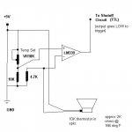
Here's the schematic for the Voice Coil temp protection.
I based it off of a safe temp of approx 166 degrees F and the specs of the Thermistor. The circuit is nearly identical to the one inside the Amplifier that protects the outputs/heatsink from overheating, just set to a different temp.
Here's the schematic for the Voice Coil temp protection.
I based it off of a safe temp of approx 166 degrees F and the specs of the Thermistor. The circuit is nearly identical to the one inside the Amplifier that protects the outputs/heatsink from overheating, just set to a different temp.
Attachments
I just wanted to add I've owned that sub before. And with a "150Wrms" amp I was able to get the coils stinky(Although I wouldn't suggest running them ported to anyone) . Those subs are extremely over rated, and inefficient. IMHO they are garbage. You can find much better sounding, looking, power handling, and more efficient for the money.
Look into a sub you can use ported in a small box tuned low. I got much more output and bandwidth with a tangband W8 740 8" sub with a 12" passive radiator in a .8cuft box than the sony in a 1cuft sealed box. With the same power.
And the tangband costs less 😉. And it handled the power better. Or maybe it was because I had to turn it up much less to match my mains 😉.
You're amp would probably be much too much power for a single 8" tang band sub, but maybe 2 of them in series would be more suitable.
You may want to look on the JBL PRO webpage they have an
article on power handeling and the danger of UNDER powering
speakers.
article on power handeling and the danger of UNDER powering
speakers.
You'll never get a motor hot enough to de-magnatize ferrite/ceramic
If you are "Underpowering" you would never blow a speaker...
Seriously, turn down the volume or buy a speaker that can handle more power...
It's simple... If you have a an amplifier that puts out 350 watts, buy a speaker that has a continous rating of 700 watts. That way if your amplifier was driven into full clipping and could (theorically) produce 2X its rated output at something like 50% distortion the speaker would survive....
Otherwise, use less power...
For the sake of argument, don't go on about clipping and cone movement, etc... I did a full test, read it here...
http://forum.carstereos.org/clipping-test-results-t47441.html?t=47441
Vent stalling
Woofers are generally cooled by forced air convection. The voice coil gap is vented, and cone motion works like a lossy pump. Like a two-cycle engine exhaust, this kind of system can be tuned. If you tune it to work best at deep bass frequencies, then the vents don't work well at high frequencies. At high frequencies, the cooling vents stall. When power is presented to a woofer at high frequencies, the cone doesn't move enough to provide effective venting. That's why higher frequencies tend to be harder on a woofer than low frequencies, where the vents are able to cool the voice coil better.
Wicking heat from the pole piece with a cooling plug helps remedy this situation a great deal, by the way. Whether the cooling vent is stalled because of high frequency or acoustic loading (via horn or other mechanism), heat can be removed from the core with a cooling plug. In fact, I'd say cooling plugs are more effective than vents in any situation where cone motion is small.
High power horn loaded speakers are improved with cooling plugs because horn loading reduces excursion. Even though efficiency is higher than direct radiators, there is still an abundance of heat. Since excursion is reduced, venting is stalled and that makes cooling plugs attractive.
Also, wide band woofers, used at low frequencies through the midrange, can benefit from having both cooling mechanisms, venting for low frequencies and cooling plugs for higher frequencies. Two-way speakers with a woofer that covers a wide band can be improved by having cooling plugs and voice coil gap vents.
If you are "Underpowering" you would never blow a speaker...
I'm not sure that's true.
I had a friend that blew some 160Wrms speakers with a 50Wrms amp.
He pushed it into clipping,and the DC fried one of his speakers,simple as that. Clipping is bad,speakers do not like DC.
- Status
- Not open for further replies.
- Home
- Loudspeakers
- Subwoofers
- Voice Coil Protection for Speakers