I need a clean small amplifier to drive a set of transformer-coupled electret headphones. I built an LM1875-based amp and was not impressed - these headphones deserve better. No Class D or tubes. Class A is attractive, but might be too large, so probably an AB design.
The requirements are simple. It's a pretty easy load to drive - see attached plot of the input impedance of the coupler. It's about 20 Ohms over most of the audio spectrum, we can call it 16.
7VRMS is enough to drive the phones to the loudest level I'd normally use, but we can double that for headroom. 15dB of gain is plenty. +-15V supplies should be fine for this. So we're talking something in the 10-15 watt range. A little more would be ok.
Ideas? I'll consider anything from a finished product to a bare pcb to build on.
Attachments

Last edited:
https://www.diyaudio.com/forums/headphone-systems/
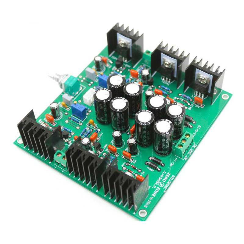
Class A: JLH headphone amplifier and JLH1969 mini (BJT), tuned to 20 ohms. Kits and ready-made assemblies are offered on Internet sites.
Class A: JLH headphone amplifier and JLH1969 mini (BJT), tuned to 20 ohms. Kits and ready-made assemblies are offered on Internet sites.
Last edited:
You might want to carefully check out Broskie's Tube Cad Journal. Yes, it's mostly about tube circuits, but he's nuts for headphones, and has included many variations on his ideas that are totally solid state designs, and might be appropriate for your intended use.
Do you really need a power amp? There are preamps that can manage what you've suggested as your requirements.
Do you really need a power amp? There are preamps that can manage what you've suggested as your requirements.
Thanks, I'll have a look. From what I've seen, 14VRMS into 16 Ohms (with a dip to 5) takes it out of the normal headphone amp territory, which is why I've posted it here. Are there headphone amps that manage that?
Something used that could be tweaked/improved would be ok, too. Such things used to be more common. I remember back in the 70's building a little Southwest Technical Products amp that I think was 15 watts per side, the 215 if I recall correctly.
Something used that could be tweaked/improved would be ok, too. Such things used to be more common. I remember back in the 70's building a little Southwest Technical Products amp that I think was 15 watts per side, the 215 if I recall correctly.
Mind you, it´s *hard* to much surpass an LM1875.I built an LM1875-based amp and was not impressed
maybe you expect too much?
Some interesting ideas there, OldDIY. I initially looked into the TPA6120 but it doesn't like the low impedances. That JLH board looks interesting; do you think that is enough heatsink?
Small adjustment - changing the values of 2 resistors and increasing the heatsinks. You can take a kit or bare board (PCB). It is possible to get with the same parts 0.5-1a/+-12-15v.
The radiator is large .Or you need an aluminum case.🙁 Potentially the same layout as JLH1996 (there are also PCB).
The above applies to any class A amplifier. Physics can be taken from the (15 Om) itself JLH.
The radiator is large .Or you need an aluminum case.🙁 Potentially the same layout as JLH1996 (there are also PCB).
The above applies to any class A amplifier. Physics can be taken from the (15 Om) itself JLH.
Last edited:
Some interesting ideas there, OldDIY. I initially looked into the TPA6120 but it doesn't like the low impedances. That JLH board looks interesting; do you think that is enough heatsink?
7.3 Recommended Operating Conditions
MIN NOM MAX UNIT
Split Supply ±5 ±15
Supply voltage, VCC+ and VCC- V
Single Supply 10 30
Load impedance VCC = ±5V or ±15V 16 Ω
Operating free–air temperature, TA
Hold on... I can't digest so fast! That last one is too small to read.
Yes, and 7.1 Max ratings says 8 Ohms, and 7.5 Electrical says output current 700mA per channel. But look at the distortion curves, distortion deteriorates as output power increases (even to 100mW!), the lowest they show is 32 Ohms for that reason. I think you would destroy it thermally running 7VRMS into 16 Ohms per channel, the pcb is the only heatsink for that package. I'm skeptical.
7.3 Recommended Operating Conditions
MIN NOM MAX UNIT
Split Supply ±5 ±15
Supply voltage, VCC+ and VCC- V
Single Supply 10 30
Load impedance VCC = ±5V or ±15V 16 Ω
Operating free–air temperature, TA
Yes, and 7.1 Max ratings says 8 Ohms, and 7.5 Electrical says output current 700mA per channel. But look at the distortion curves, distortion deteriorates as output power increases (even to 100mW!), the lowest they show is 32 Ohms for that reason. I think you would destroy it thermally running 7VRMS into 16 Ohms per channel, the pcb is the only heatsink for that package. I'm skeptical.
#24 #48 #55 SINCLAIR Amps from c1972
Any simple AB amplifier, starting with Lin.
#10 The LM1875 for best
#4 #9 Semi Non-Switching Output Stage of LM3886 Clone
Any simple AB amplifier, starting with Lin.
#10 The LM1875 for best
#4 #9 Semi Non-Switching Output Stage of LM3886 Clone
Last edited:
Why do you use a transformer and no direct drive? For reasons of safety?
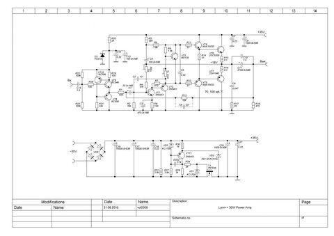
I think my 20 W in 8 ohm non-switching class-AB amplifier with class-AB bias loop would be suitable:
Marcel van de Gevel, “Audio power with a new loop”, Electronics World incorporating Wireless World, February 1996, pages 140...143
https://worldradiohistory.com/UK/Wireless-World/90s/Electronics-World-1996-02-S-OCR.pdf
Unfortunately some of the parts are obsolete now.
Last edited:
Why do you use a transformer and no direct drive? For reasons of safety?
These are electrostatic (pre-polarized electret) headphones. The transformers are 50:1 stepup, providing over 350 volts at normal high listening levels.
I'll take a look at your amp, thanks.
- Home
- Amplifiers
- Solid State
- Wanted - good clean 10-15 Watt AB stereo amplifier