Hi,
So i have a 2.1 Computer speaker system with one woofer and 2 speakers. Lately one of the speakers have started to sound less than the other. It happened before some 3 years ago the then technician replaced the ICs and the problem was sloved. This time i am planning to do it myself. I opened the system and found three ICs, One of them was LM1875T and two other were TDA2030. My question is shouldn't all three of them be the same? either LM or TDA's ?? And with what ICs i should replaced them now LMs or TDA's?
Note this setup is not factory setup as an aftermarket service has be done the system so we can't say if the technician replaced with the exact factory replacement or with something he found easily, at that time.
Secondly, i tested the diodes too, they have never been replaced, they are all shortcircuited, should i replace them too? or it'll work without replacing them?
Please advise. thans
Hi wasim,
In my opinion (and without a shematic of your system) the LM is used because it delivers more power than the TDA, necessary for the "subwoofer"..
The amps needn't to be the same, because they power different types of application.
In front of the amps should be an active filter with a buffer that splits the frequency band to sub and satellites.
Maybe a resistor or a capacitor is blown...if you want to repair it on your own you need the plan of the circuit.
I don't think that anyone knows which diodes you are talking about. As far as I know you can use diodes on the TDAs for stabilizing the gain but they can be used for different tasks, too. When you say shortcircuit, do you mean that they are physically bridged or did you measure them and you found a ahort?
Hi wasim,
In my opinion (and without a shematic of your system) the LM is used because it delivers more power than the TDA, necessary for the "subwoofer"..
The amps needn't to be the same, because they power different types of application.
In front of the amps should be an active filter with a buffer that splits the frequency band to sub and satellites.
Maybe a resistor or a capacitor is blown...if you want to repair it on your own you need the plan of the circuit.
I don't think that anyone knows which diodes you are talking about. As far as I know you can use diodes on the TDAs for stabilizing the gain but they can be used for different tasks, too. When you say shortcircuit, do you mean that they are physically bridged or did you measure them and you found a ahort?
Hi there,
I have doubts about the capacitors - they are supply capacitors, they are not bludged but they don't look good either - so i am replacing them with same new items. All other caps. are good, well atleast they are looking good and strong (i don't have capacitance meter). On the other hand, i visiually inspected the resistors and none of them looks brownish, black or burnt. About the diodes, yes I tested them with the multimeter they all are leaking i.e short.
Now I want to ask how can I test the ICs ? (I know there are some special tools for that but i don't have them, so any method of testing with a multimeter will be a way out). And Since all the diodes are short should I replace them or is it ok to leave them like that?
Replace all with the LM1875. The TDA ICs were discontinued a couple years ago. Although you will see the TDA parts available, they can be counterfeit Chinese parts. Buy the LM1875 ICs from a supplier like Digikey or Mouse (I don't know your local) to insure authentic parts.
No you will not get higher output power despite what was said because the power supply voltage is the same, so using the 1875, you get the same output (well, within a watt anyway).
What diodes are you referring to? The ones across the TDA2030 output? Something funky is going on if those are getting shorted. They would short the supply rails if truly shorted. The LM1875 includes them internally, so they can be eliminated from the circuit.
Last edited:
*IF* any diodes (supply or anti flyback) diodes were actually shorted, that amp would be happily blowing fuses all day long ... yet it apparently works, so I'd take your measuring with a grain of salt.
Why do you say they are shorted?
If at the power supply, you might be measuring the secondaries very low resistance.
Why do you say they are shorted?
If at the power supply, you might be measuring the secondaries very low resistance.
let me give you guys the pictures of what i am having.
The snaps are self explanatory
http://s22.postimg.org/v6rqdw27l/image.jpg
http://s22.postimg.org/9a9sr9eep/image.jpg
http://s22.postimg.org/gssxzw5rl/image.jpg
http://s22.postimg.org/dsh5gh0s1/image.jpg
http://s22.postimg.org/i4acj7x2p/image.jpg
I am testing the diodes with a multimeter by the way after setting my multimeter on diode mode I probe Negative lead of the multimeter on the silver strip side of the diode and Positive lead on the other side of the same diode it shows values around 700 and when i reverse the probing leads it again shows readings on the multimeter which to my understanding means the diode is short as it is conducting both ways where it should be conducting the electricity one way only. Do tell me if I am doing it wrong or missing something.
Thanks Regards.
Attachments
This is normal for measuring a fullwave diode bridge in circuit. You get the normal diode drop voltage in one direction (forward bias) and "some reading" in the reverse. The reading may increase if the small current from the meter is charging the filter caps. This implies you are measuring across each diode and not the opposite ends of the bridge.
Hmm right, so best way of measuring/checking a diode is to remove it from the circuit and then subject it to tests ?This is normal for measuring a fullwave diode bridge in circuit. You get the normal diode drop voltage in one direction (forward bias) and "some reading" in the reverse. The reading may increase if the small current from the meter is charging the filter caps. This implies you are measuring across each diode and not the opposite ends of the bridge.
Plus Anything on the problem I wrote about?
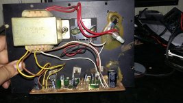
please post bottom side pics also. what is the voltages output of the transformer. I see there is two center tapped windings for sub and sats amplifiers.if u could post the bottom pics we can get the schematics of your 2.1 system.
And why only 1 amp diodes?Why 1kV diodes?
Anyway, The diodes in the picture appear to be heftier. Probably the three amp type.
please post bottom side pics also. what is the voltages output of the transformer. I see there is two center tapped windings for sub and sats amplifiers.if u could post the bottom pics we can get the schematics of your 2.1 system.


Some pics that might help
I don't know. How can I know that?are those set of diodes 1n4007 types?
they are 4007 diodes. if you happened to desolder it, you can see the name on the body of the diode. doides never short. they work unless over heated and cracked. if your transformer is above 2 amps then change the rectifier diodes(1n4007) to 1n5402.
they are 4007 diodes. if you happened to desolder it, you can see the name on the body of the diode. doides never short. they work unless over heated and cracked. if your transformer is above 2 amps then change the rectifier diodes(1n4007) to 1n5402.
so i should leave the diodes as they are. And change all 4 power capacitors with new ones and change the ICs to LM1875T - all three of them. and call it a repair?
changing the power capacitors is ok. but changing all 3 ic's needs to increase your power supply also. yours is 2amp transformer with two sets of center tapped windings. one for tda2030 satellites and other for lm1875 sub.the both are 1 amp each. may be your sub box is not enough to put bigger transformer.
first change the power supply caps which you want to change. turn on the system and listen to some of your songs to make sure the amps sound clearly both high and low.
first change the power supply caps which you want to change. turn on the system and listen to some of your songs to make sure the amps sound clearly both high and low.
WRONG, diodes DO short and it happens all the time.they are 4007 diodes. if you happened to desolder it, you can see the name on the body of the diode. doides never short. they work unless over heated and cracked. if your transformer is above 2 amps then change the rectifier diodes(1n4007) to 1n5402.
Some might explode and crack the plastic casing, some will not, that doesn't mean they are any healthier.
Only a diode test can tell for sure.
By the way,that's why it's included in Multimeters 🙄
How can test them with a multimeter without having to desolder them?WRONG, diodes DO short and it happens all the time.
Some might explode and crack the plastic casing, some will not, that doesn't mean they are any healthier.
Only a diode test can tell for sure.
By the way,that's why it's included in Multimeters 🙄
- Status
- Not open for further replies.
- Home
- Amplifiers
- Chip Amps
- What are best ICs to replace for 2.1 Computer speaker Subwoofer system.