SO what the heck is this, exactly? Electronic Choke
What exactly is it really? A capacitance multiplier? Or some high-speed switching device? Something closer to a solid-state light ballast?
The link to E-choke Design has nothing at all about the design of the e-choke, it's all about performance and how to use it, which seems to be a lot like a capacitance multiplier.
http://www.tentlabs.com/Components/Tubeamp/page44/assets/E-choke%20design%20UK.pdf
It never talks about the voltage drop across it. It usage instructions sound a lot more like a capacitance multiplier than a choke. It sits between two filter caps...if you put it directly after the rectifier does it have the lower voltage output and improved regulation of a choke? Or is it, like a capacitance multiplier, not really suitable for conditions where the input drops all the way to 0?
Al the secrecy, voodoo, and made-up names makes me wary. But if it's really just a PCB for a capacitance multiplier, I could really use one for a class-A amp. But...will it really make a higher-order filter or just a lower knee? I'd need to know what it is nd how it works in order to use it appropriately or optimally.
Does it have something to do with the gyrator-capacitor model of a magnetic circuit? Am I reading too much into this?
A choke is an inductor.
By my guess, E-choke is probably just a gyrator, i.e. a simulated inductor using opamps and capacitor.
By my guess, E-choke is probably just a gyrator, i.e. a simulated inductor using opamps and capacitor.
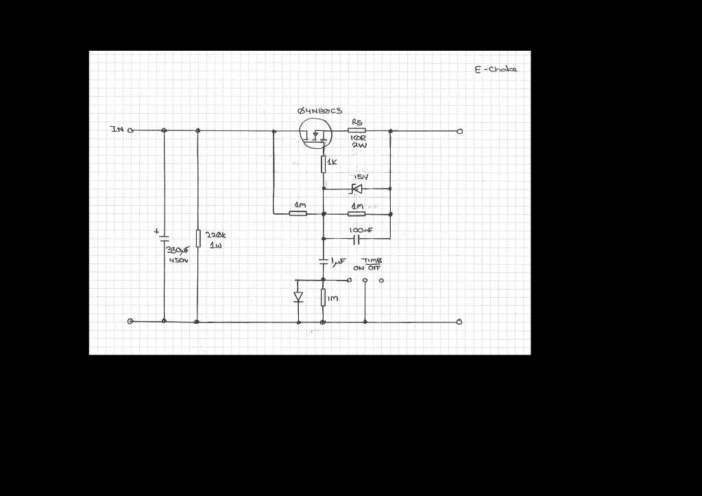
http://www.diyaudio.com/forums/atta...ower-supply-mosfet-vs-choke-filter-echoke.jpg
That;s from searching further and finding post 8 by gingertube in http://www.diyaudio.com/forums/tubes-valves/261117-power-supply-mosfet-vs-choke-filter.html
so now I've got to learn how the heck that circuit works in order to really figure out how to use it optimally.
Thanks to some great animations, I understand the stengths and weaknesses of a capacitance multiplier. Now I've got to get similar background on these FET Gyrators and their strengths and weaknesses. Then...can they be used together...and if so exactly how & when...or when is a FET filter better, and how to incorporate a real regulator?
So why all the secrecy from Mr. Vanderveen and Tentlabs? Why not make DIY products that educate?
Last edited:
I'm lost. So how does that circuit work? Anyone got some magical links that will help me understand?
These are cap multipliers, not actually gyrators.
Here is an example of true gyrator: if you analyze the circuit, it is obvious that it tends to behave like a choke: for short term variations, it behaves like a constant current source, but on the long term, it is a short circuit (except for the drop-out voltage).
Of course, such a simple circuit does not perform very well: the MOS has a low transconductance, and a finite output resistance.
It can be augmented, by using BJT's as actual operational devices (they have a higher gm) and cascoding the MOS.
Note that this circuit is a two-terminal device, just like the real thing
Attachments


Looks all the way like a capacitance multiplier.
Will replace a choke, with advantage, as a ripple killer.
Say, between 2 capacitors.
Will not replace a choke in the input of a supply, between diodes and first cap, because it can not store energy to be released later, like an inductor does.
In fact, even the "capacitance multiplier" name is misleading, because it does not store gobs of energy like a really big cap would, all it does is lower ripple.
Is it a scam?
No if all you need to replace is, say, a screen filter supply choke or make a low hum preamp.
Of course, you can build your own for 1/4 the price .
- Status
- Not open for further replies.
- Home
- Amplifiers
- Power Supplies
- What is a "Electronic Choke"