If they are inside or near a radio, they are probably meant to prevent rattling sounds due to unintended amplitude modulation by mains harmonics. If so, the Dutch word for them is ratelcondensator, rattling capacitor.
The chassis of the radio and the mains wiring can act as an antenna (aerial). The capacitance between the primary and secondary windings of the mains transformer will couple any RF signals picked up by the mains wiring to the secondary side. The time-varying differential resistance of the rectifying diodes will amplitude modulate the RF signals, and they can be transmitted back via the mains wiring. This can cause rattling sounds in radios, shorting the diodes for RF with a capacitor can solve that.
The chassis of the radio and the mains wiring can act as an antenna (aerial). The capacitance between the primary and secondary windings of the mains transformer will couple any RF signals picked up by the mains wiring to the secondary side. The time-varying differential resistance of the rectifying diodes will amplitude modulate the RF signals, and they can be transmitted back via the mains wiring. This can cause rattling sounds in radios, shorting the diodes for RF with a capacitor can solve that.
A poorly understood piece of engineering. Transformer secondaries have sufficient leakage capacitance and inductance with very low damping resistance to cause RF ringing when a rectifier diode stops conducting. Those bypass caps are meant to "cure" the ringing but only make it worse. The solution is to place a lowish value resistor across the secondary to damp the ringing (note that only a resistor will damp oscillation and reactive components will only make it worse). A capacitor in series with the damping resistor will limit the mains frequency current to a safe level while offering a short circuit to the RF.
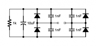
The rectifier I posted is from the heater supply of a tube line stage. It then feeds a voltage regulator. "Rectifier 2" (attached) is the rectifier for the unregulated B+ supply for the same unit (NOTE: Capacitor values "not to scale").
Johno: Are you describing something like what I have depicted in "Rectifier 3"?
Johno: Are you describing something like what I have depicted in "Rectifier 3"?
Attachments

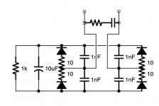
I was taught they are for slowing down the sharp turn-on and turn-off of the diodes, reducing possible hf current spikes. They are not intended to snub energy and therefore have no resistor in series. A snubber R-C across the transformer secondary does the snub job. The RC is seen in your 'Rectifier3' picture.
I was used to seeing an R-C circuit in parallel, not series. Is there a simple explanation for when you'd use each configuration?
- Home
- Amplifiers
- Power Supplies
- What is the purpose of the capacitors paralleling the diodes in this rectifier?