As some of you allready have seen, I have encountered a massive breakdown on one of my power amplifiers. In order to avoid (or at least try to avoid..) future events like that, I would really want to hear your theories about what could have happend.
The stor was like this, I was running this amp on a disco as a subwoofer amplifier driving two paralelled 18" subwoofers. The amp was running in bridge mode and the total load impedance was 4ohm (2*8ohm). The amp was rated 1500w RMS in bridge mode @ 4ohm.
The sound level was moderate at this time so I didn't push the amp so hard. And than suddenly, HMMMMMMM and then blackout (mais fuse 16A blown). When I investigated the amp I found 10 out of 16 power transistors shorted.
I allso found one emitter resistor (0,33ohm) witch was infinate resistance. I'm pretty shure that the transistor witch was connected to that resistor was one of the few "survivers".
Can the faulty resistor caused all this ? I mean, can the breakdown of one device cause so much unbalance so it starts an an chain reaction of transistor breakdowns, or was this a case of spontaniouse combustion ?
Is bridge mode more stressfull for the output transistors ?
/Peter
Attachments

Hi Peter,
Sorry to hear of the demise of your amp. Sounds like your transistors got cooked: their safe operating areas were exceeded. The open-circuit resistor might be a cause - if it went open-circuit then presumably only 3 transistors would be sharing the load rather than 4. But IME resistors don't just go open-circuit - this is a typical symptom of severe current overload due to a transistor failure. Is the resistor scorched?
Consider the powers involved in bridge mode:
With +/-80V psu rails and a 4-ohm load, the maximum average load power, at full volume, would be about 3000W. But the worst case dissipation for the transistors will occur at much lower volume when the 4-ohm load is dissipating 1300W. At this point the power transistors, in total, will also be dissipating 1300W. In bridged mode, according to your schematic, there will be 16 power transistors sharing the work. So, on average, each will disspate 1300/16 = 83W, and each will have a peak dissipation of about 100W, and each a peak Ic of about 6.4A.
At maximum output power, the peak Ic per device will be about 10A.
This assumes the load is 4-ohms resistive.
BJTs generally fail for one of three reasons: the silicone die gets too hot - usually needs to be <<200C, secondary breakdown occurs due to excess current and voltage, or the bond wires melt due to excess current.
If you know the transistor type you can check these figures against the SOA (safe operating area) chart on their datasheet. You'll have to estimate the temperature of their cases as their performance degrades very quickly with temperature. This is tricky - you'll need to estimate the room temperature at the time and the thermal reistance between heatsink and air and so on. Does the amp have any temperature cut-off device or other temperature limiter?
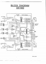
Is the schematic that you posted actually from the amp you are using ?
I am asking because in this case it might not be that good for sub-use because of this coupling x-former used for base-drive. OTOH it of course depends on the correct dimensioning of this x-former.
Have you got any frequency-response data ?
Regards
Charles
I am asking because in this case it might not be that good for sub-use because of this coupling x-former used for base-drive. OTOH it of course depends on the correct dimensioning of this x-former.
Have you got any frequency-response data ?
Regards
Charles
This amp is old, old, old.
I got news for you, things die, they don't live forever.
When an amplifier is advertised as being "able to run 2 ohms" it really means "will sound good and run for a long time into 4 ohms" and every now and then run it at 2 ohms in an emergency.
Life-span halves with every 10*C difference. 8 ohms is probably Delta 40*C, 4 ohms 80*C, 4 ohms bridge 160*C. Say the life is 10,000 hours at 40*C, it will be 625 hours at 80*C, and a whopping 39 hours at 160*C (change in transistor junction temperature above ambient).
You were just asking for it.
Was it really 4 ohms?
I doubt it. Most 8 ohm woofers measure 5R6 or so, and it is nor a resistive load either.
"The sound level was moderate at this time so I didn't push the amp so hard"
Too bad, it might of held up longer.
Class AB amplifiers run their hottest at about 25% of rated power.
Replace ALL of the outputs at the same time, I would go new emitter resistors and insulators too.
Replace the driver IC too, its about shot, and it costs little or nothing.


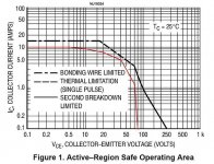
Find attached a SOA graph for MJ15024.
I have sketched the operating curve for each of the 8 output devices, in bridge mode and driving a 4-ohm resistive load.
To draw the operating curve, I choose a Vce for a transistor, then work out the load voltage as 80 - Vce. Then the load current as (80-Vce)/2. It is 2-ohms not 4 that the amps "sees" in bridged operation. The Ic is the load current divided by 4 as there are 4 transistors per half. This is somewhat conservative because it doesn't account for the voltage drop across the emitter resistors.
The upshot is that, at 25C case temperature, your operating line is fine for a 4-ohm resistive load in bridged mode. The maximum power dissipation of MJ15024 is 250W and yours will be 200W peak. With thermal derating, you can still operate ok up to 60C case temperature.
The load must no go much below 4-ohms and must not be capacitive otherwise the SOA will be breached and devices will fail. Note that the worst case amplitude for the transistors is about 51V (not 80V) so they will work hardest when the output power is about 1300W (rather than full power of 3200W).
Now, having said it'll be ok, you need to keep those case temperatures below 60C at all times. The total power dissipated by each amp will be about 650W average and that is a hang of a lot of power to get rid of, especially in a hot sweaty disco. I think this is somewhat unrealistic and you'll have trouble.
As a precaution I'd check that there is a mains thermal cut-off switch located on the heatsink close to the transistors and rated at 50C or so to be on the safe side. This way if things get too toasty the amp will turn off before the transistors fail. Also test the amp to make sure the fans still work!
Attachments
Erratum
In post #2 I said the peak power of each transistor would be 100W. This should have said 200W.
In post #2 I said the peak power of each transistor would be 100W. This should have said 200W.
The load must no go much below 4-ohms and must not be capacitive otherwise the SOA will be breached and devices will fail.
Not even one of these two requirements might be properly met when driving a speaker at sub frequencies.
DC resistance may very well drop to 3 Ohms. Around peaks the impedance looks either inductive or capacitive.
Regards
Charles
Yes I agree Charles. I think the mfr's spec is somewhat ambitious regarding bridging.
Do you have a rule of thumb for estimating the worst equivalent speaker loading? For example, dividing the nominal Z by two - so if you are intending to bridge with a 4-ohm nominal speaker you should design the amplification system to work ok into a 2 ohm resistive load.
Do you have a rule of thumb for estimating the worst equivalent speaker loading? For example, dividing the nominal Z by two - so if you are intending to bridge with a 4-ohm nominal speaker you should design the amplification system to work ok into a 2 ohm resistive load.
Do you have a rule of thumb for estimating the worst equivalent speaker loading?
No I don't unfortunately. But there are manufacturers with generously dimensioned output stages of which they claim should be able to drive 1 Ohm. I think such an amp is hard to be killed by two paralleled 8 ohm drivers under any conditions.
The other solution is SOA protection in the output stage, i.e. a current limiter that takes voltage accross the devices into account.
There was a quite good article in EW+WW, written by a member of this forum, dealing with SOA protection.
Regards
Charles

Isn't it that if you bridge the amps over 2 paralleled 8ohm speakers, then you get 2 ohms per amp?
2 paralleled 8ohms = 4 ohms
bridged = each amp drives the "half" of the impedance...
Or am I completely lost😕
Cheers
Tino
Isn't it that if you bridge the amps over 2 paralleled 8ohm speakers, then you get 2 ohms per amp?
This is 1.) right and has 2.) already been mentioned.
Regards
Charles
That's right Tino.
Charles' example happens to fit the axiom of designing the system to work into half the nominal impedance.
If we use this as a working rule of thumb, Peter should never use his amp in bridge mode with less than 8-ohm load, and even then he needs to keep it really cool!
This assumes there isn't any SOA protection circuitry.
BAM
This assumes there isn't any SOA protection circuitry.
Which there actually isn't in pflodin's case, if you have a look at the schematic.

regards
Charles
phase_accurate said:
This is 1.) right and has 2.) already been mentioned.
Regards
Charles
Sorry that I have bothered, I didn't get that, too much of "diagonal reading"

OK, I have just been soldering in 16 new transistors and 16 new 0,33ohm resistors, but I feel a little shakey about actually putting the plug in the outlet.......
If I understan you folks right, it's not "safe" to use this amp the way I did. But if I use it as an stereo amp and connect one speaker to each channel, I will have a total of 600W (300Wx2 @8ohm) output instead of 1500W (8ohm/2 = 4ohm load) so bridging it was really attempting. But I now see the dangers with it. Maybe I should swap places with the other amp witch I use for my highrange boxer since that load should be a little less painfull and use that amp for the subs..( It's a Behringer EP1500 witch have similar data but is much newer, might eve be a MOSFET amp, I don't know..)
I don't think i can avoid putting the plug in the wall any longer now ,
/Peter
BTW, how about the adjustments (VR3 VR4 VR5 in the schematics), think I need to adjust them ?
/Peter
/Peter
- Status
- Not open for further replies.
- Home
- Amplifiers
- Solid State
- What makes a power amp fail...