My venerable AX-500 is a bit under the weather. It used to take a couple of seconds for the amp to "click" and switch the speakers on, in the past couple of days is has gone weak on the left hand channel. It does still work, but at a much lower volume. I have used different inputs, the B speakers and swapped left / right on the speakers and the problem remains
Suspecting blown caps I have taken the top off and taken a photo. The 12000 uF capacitors have been dusted clean, the rest of the board blown clean. It appears that the rear capacitor has been leaking and indeed the top of it is slightly convex. The smaller 470uF capacitor is not bulging, but the different colour around its base suggests to me that that has been leaking too.
Could someone confirm the diagnosis, suggest any further tests to be done, or even a place to get suitable replacement components - the main caps are nichicon 85 degree
Last edited:
30 years old - definitely time to recap the electrolytics without a 2nd thought, though obviously the leaking ones are first priority - get them out and clean the pcbs thoroughly, replace, reset the bias. That staining is clearly leakage, and its going to corrode the other components if left.
I'd suggest careful scrubbing/rinsing with IPA to remove the deposits. Old toothbrushes are great tools for this. Don't immerse the board, though, and remember alcohols like IPA are flammable, always work in well ventillated area.
While at it check the solder joints visually for issues.
I'd suggest careful scrubbing/rinsing with IPA to remove the deposits. Old toothbrushes are great tools for this. Don't immerse the board, though, and remember alcohols like IPA are flammable, always work in well ventillated area.
While at it check the solder joints visually for issues.

That was quick, thanks for confirming the staining is electrolyte.
I have been doing a search for replacements, but am unable to find any "matching" equivalents so far. One part that is particularly throwing me is the reference to 65wv on the case. What is that specification - I could not see a voltage spec elsewhere on the case.??
I still like the sound of the amp so would want to replace with something that will dynamically be the same, any pointers on where to shop, or is it just a matter of buying on specification ?
(I don't know that much on electronics , but carry around a bit of knowledge that Nichicon are very good, Panasonic also good but maybe slightly porer quality.)
Last edited:
I would replace C157/8 the 100u 6v3 feedback capacitors and the three next to the hot spots on the board (Q117 vicinity). The main smoothers will read perfect unless leaking fluid.
Check for dry joints and replace the bias pots. Clean the controls with Servisol Contact Lubricant and all will be well for another 30 years.
Check for dry joints and replace the bias pots. Clean the controls with Servisol Contact Lubricant and all will be well for another 30 years.
Its not always easy working from photos...
Tbh the black gunge looks more like glue, something manufacturers were particularly fond of to secure items like these caps. The convex plastic cap could well be just that, convex plastic and doesn't necessarily imply an issue. In any case, the caps are common to both channels.
I would try and diagnose and repair the fault rather than replacing parts in hope.
The gain of the amplifier is set by just a couple of components in the feedback circuitry and its pretty rare for there to be actual gain faults.
Jon mentions a couple of 'feedback' caps and without looking at the circuit would assume these to be in the feedback return... so yes, a possible problem area if one had failed although I somehow suspect your issues may lie elsewhere.
Checking each channel receives an identical input signal (at the power amp) is seconds work with an oscilloscope and removes all guesswork.
This reminds me of a Yamaha AX-380 I just recapped from original parts 30 years old.
All capacitors will benefit from improving the sound. Those vw are the voltage on old Nichicon caps. Never replace any caps with lower voltage and can benefit from higher voltage as long as they fit without coming in contact with any other components or top chassis. Also make sure you mark the negative side of the cap on the board from existing caps in place as sometimes the board are incorrect.
Panasonic FC/FR are great for power supply caps and Nichicon are great for signal paths. You can't go wrong with those in general.
I also replaced the resistors close to the analogue output which did improve the sound with MOX resistors but can be difficult so I couldn't recommend it until you have experience in replacing components.
Good luck, take your time. Those big caps can hold voltage that will harm you so make sure you discharge them with one hand
If the 100u 6v3 feedback capacitors 'leak' electrically, the protection will sense DC on the output as the capacitor tries to charge up and hold RY101 off because it won't allow output DC to reach one side of the differential input pair that are responsible for 0volts balance on the outputs.
Thanks so much - I am listening to all comments, but thought I should respond to Mooly so you get a better appreciation of my knowledge
Agreed, I have tried to diagnose the problem with my ears, and eliminated the speakers and inputs at least, so I think that leaves the pre power and power sections (at risk of apparently overstating my understanding of the circuitry here)
It would, but I don't have a scope, and even if I did I don't have the training / experience to use it. 🙁 Unfortunately.
I do have a couple of half decent electrical multimeters and do know how to use that, if there were some diagnostic test to confirm the diagnosis. There is a capacitor tester function., but how accurate that will be I don't know
I understand, but it's the best I can offer I thinkIts not always easy working from photos...
I would try and diagnose and repair the fault rather than replacing parts in hope.
Agreed, I have tried to diagnose the problem with my ears, and eliminated the speakers and inputs at least, so I think that leaves the pre power and power sections (at risk of apparently overstating my understanding of the circuitry here)
Checking each channel receives an identical input signal (at the power amp) is seconds work with an oscilloscope and removes all guesswork
It would, but I don't have a scope, and even if I did I don't have the training / experience to use it. 🙁 Unfortunately.
I do have a couple of half decent electrical multimeters and do know how to use that, if there were some diagnostic test to confirm the diagnosis. There is a capacitor tester function., but how accurate that will be I don't know
A typical DVM possibly may be usable on its lowest AC range but you would need to be sure it could read low level sine test signals with some repeat-ability. Typical these might be just a few 10's of milli volts. You would also need a mono test tone of around 400Hz which is easily made using Audacity and can be an MP3/WAV/WMA file as desired.
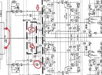
I'm tempted to say that you should just try shorting the inputs together which would guarantee equality. The circuit also seems to have an error, an omitted coupling cap on the input to one channel.
Its also possible one of the muting transistors is leaky which would cause a reduction in level.
If you short the wipers of the volume control as shown then that forces an equal signal at that point. If the level is still different between channels then remove the two muting transistors and retest. If its still different then change the two caps Jon mentioned.
If that's still no good then you need a scope to do more thorough testing 🙂
Attachments
Those errors are common in the drawing of Yamaha, Sony and other major manufacturers schematics.
We were always told about them on the manufacturers courses, I think they are there on purpose, to point out to other engineers that they need to attend the training courses.
Sharp were the worst, if I remember correctly.
Good fun, not!
We were always told about them on the manufacturers courses, I think they are there on purpose, to point out to other engineers that they need to attend the training courses.
Sharp were the worst, if I remember correctly.
Good fun, not!
Ah, thanks for that comment Jon, I now understand the response from Mooly and the annotations on the wiring diagram.
I will look at dismantling the amp over the weekend with a bit of luck. I should then be familiar with the specific caps mentioned - I guessed that you had referred to a schematic as I couldn't see all those references on the photo 🙂
Thanks
I will look at dismantling the amp over the weekend with a bit of luck. I should then be familiar with the specific caps mentioned - I guessed that you had referred to a schematic as I couldn't see all those references on the photo 🙂
Thanks
OK, probably a long post, partly for my own documentation having spent a good few hours finding my way around the circuit boards today.
I have also found and downloaded a service manual for the AX-500 which has been a help in understanding some of the advice so far.
I have managed to locate the components Jon suggested, the three caps near Q117 are as follows, ratings from the parts list:
C187, 470uF, 80V
C201, 100uF, 16V
C191, 220uF, 35V
and then the much smaller C157/C158, 100uF 6.3v.
I have attached a photo of the area near Q117. Jon commented that it was the "hot" area. Is the blackening of the board normal and that's why it was called hot ? (No cleaning yet)
I have also found the Q137 and Q138 muting transistors and have looked at performing the test that Mooly suggested. I haven't done that because I am not confident that I have correctly identified where to make the short, whether on the main board or the front board which is still behind the cover panel.
By the way, the SM I downloaded shows the corresponding R155. I'm not sure what the etiquette is for uploading that, but I would be delighted to share that back with you.
The amp is partly disassembled for access but I have a couple of other thoughts before I start wielding a soldering iron about
1. I did not do a test with headphones. If I reassembled and did this will it likely say anything useful
2. From the SM I have read that the idling current adjustment is set using VR107/VR108 (does this relate to the earlier "reset the pots" comment). Is there any value in reading those values now.
One further comment, I did notice on a couple of occasions that there was a change in volume on the weak left channel, let's say it varied from 20% of the correct volume to 30% for a period, and then dropped back to 20% again. Does that help in the diagnosis.
Thanks again for any advice
Last edited:
Discolouration is normal on 'paxolin/resin' type boards such as yours appear to be, less so on fibre glass. Its just a chemical change in the material in response to heat.
Have you given the boards/leads/switches a good prod, poke and waggle to be sure the problem isn't something physical?
Testing with headphones is fine... you'll soon know if the fault is consistent or not.
Bias adjustment has no effect on this problem and as such I wouldn't start re-adjusting anything in that department.
The service manual is probably to large to attach to the forum but you can post screen snips of it if you want.
I suppose everything has had a decent bit of disturbance now, with all of the rear boards being off. I did the usual wiggling on the controls and using different inputs before concluding something more than contact spray was needed.
Everything else seems to be OK, except for some crusty golden stuff (flux residue?) between the terminals on some the big MOFSETs (I think that's what they are anyway) . I just removed that with a fingernail
I think I'll reassemble tonight and try to do the headphone test tomorrow. A bit more studying on how to do the volume control equalisation too. I'm fairly methodical, especially when learning 😉
I have sent a PM with a link to the manual - if anyone else wants it just ask
Another quick test if your meter is up to it would be to apply a test tone as I mentioned earlier and just measure the AC voltage going into each channel. Measuring on the left hand end (as drawn on the diagram) of R113 and R114 would be ideal for that.
You should see the same AC voltage for each channel. No need to have speakers or headphones connected for that. Just start with the volume on minimum and turn it up a little. You should see a few tens of millivolts AC.
I can do you an MP3 test tone and post it here in seconds if you want one.
You should see the same AC voltage for each channel. No need to have speakers or headphones connected for that. Just start with the volume on minimum and turn it up a little. You should see a few tens of millivolts AC.
I can do you an MP3 test tone and post it here in seconds if you want one.
I would replace C157/8 the 100u 6v3 feedback capacitors and the three next to the hot spots on the board (Q117 vicinity). The main smoothers will read perfect unless leaking fluid.
Check for dry joints and replace the bias pots. Clean the controls with Servisol Contact Lubricant and all will be well for another 30 years.
Agreed. Large low voltage electrolytic caps have the highest failure rate, and in the feedback path, they have near zero voltage to maintain the electrolyte, and temporary output DC at startup and shutdown will over voltage and reverse voltage those caps. Some amps have diode clamps on thee caps for that reason. Normal operation can put AC on these caps that will destroy the electrolyte.
When these caps fail, they develop impedance, ESR, that causes more feedback an reduced gain.
The same is true to a lesser extent of the input coupling caps. When the gain is affected, you are looking at caps in the signal path, not power supply caps. When power supply caps fail, you get hum, noise and instability but the gain is probably not affected.
PS: I assume you have re-seated and sprayed all connectors. Connectors (and pots) oxidize and cause noise and loss of gain.
Last edited:
Discolouration is normal on 'paxolin/resin' type boards such as yours appear to be, less so on fibre glass. Its just a chemical change in the material in response to heat..
Translation: the board material slowly turns to charcoal. Eventually the board will get as leaky as 30 year old capacitiors (electrically). Even worse when damp. When you see this happening, you need to do something to improve heat dissipation and air flow in the area to keep it from getting worse. Add heat sinks, replace resistors with bigger ones and have them sit further up in the air, even replace transistors with bigger types if the circuit can manage it (say, a power supply regulator). If it’s really carbonized, say after a massive failure, you want to actually scrape away the carbon. In any case, you want to reflow the solder joints and clean the area as they may be getting oxidized.
Translation: the board material slowly turns to charcoal. Eventually the board will get as leaky as 30 year old capacitiors (electrically)........
Its a long long way off that point 😉 Its a normal if unsightly discolouration on something like this. I was a bench tech for many years and this was the norm with even big name manufacturers acknowledging the condition.
Another quick test if your meter is up to it would be to apply a test tone as I mentioned earlier and just measure the AC voltage going into each channel. Measuring on the left hand end (as drawn on the diagram) of R113 and R114 would be ideal for that.
OK, newbie question, I have found the resistor on the schematic, where am I testing the voltage difference between. From the resistor to another connection, the chassis or across the resistor itself ? I'm happy with vehicle electrics and mains testing,where's the corresponding neutral /earth to use the -ve probe on.
The same is true to a lesser extent of the input coupling caps. When the gain is affected, you are looking at caps in the signal path, not power supply caps. When power supply caps fail, you get hum, noise and instability but the gain is probably not affected.
PS: I assume you have re-seated and sprayed all connectors. Connectors (and pots) oxidize and cause noise and loss of gain.
It's certainly signal path, not power supply caps.
As yet, other than removing the residues from the MOFSETS I have not done any remedial work. I did set about removing the main board this morning, but came to the conclusion that would not be possible without desoldering connectors and cables, so I simply removed mounting screws to get better access.
This is 1980's construction, so no removable connectors - or they are so stiff I dare not exert any more force.
Even the extended selector push buttons onto the switches seems to be firmly attached and there seems little point breaking things unnecessarily. It's a nice touch that the ventilated base plate is removable, meaning it is possible to replace components with the board in situ.
- Home
- Amplifiers
- Solid State
- Yamaha AX-500 amp