I recently could acquire a pair of Quad IIs in need of restoration for a very decent price although without the tubes. I want to share my thoughts on and experiences during the restoration and would of course like to get a few opinions.


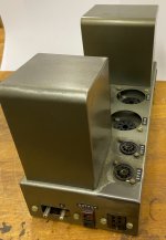
Both amps are not very clean - pictures of one of them are attached. One of them (pictured) had at some stage the resistors and the cap on the tag board replaced. It also has an additional fuse for the power tubes. The other one seems pretty much original with all the original resistors and caps.
My goal is to keep the amps as much in an original state as reasonably possible and do not make any irreversible changes, which of course rules out any changes to the chassis and keeping all the original parts even if they are no more used. On the other hand I will do an upgrade to modern safety standards which implies proper use of mains ground amongst other things. I will not use the Quad 22 preamp.
Chassis:I will add a notebook style connector with 3 poles using a 3d printed adapter. The fuse holder will be replaced by a modern one and fitted with a 3d adaptor. A mains switch will be put in the opening of the old mains connector again with a 3d printed adapter and finally a RCA socket in place of the 6 pole connector again, guess what, with a 3d printed adapter.
The chassis must have been spray painted at some point in the past and cleaning it removes the paint anyways, so a repaint is in order.
Tag board: Here I am yet unsure if I should replace it completely with a PCB or try to clean it and just replace the components - it is really very grimy. Any opinions?
Power tube sockets: Yet unsure if I should reuse them or replace them with either screw mounted sockets or also creating a small PCB. Currently I tend to reusing them.
Wiring loom: There may be some risk of broken insulation, but I would take the risk if I keep the tag board. Of course it is also grimy....
Filtering caps: They are no more in really good shape, so I will probably create a PCB for it and a 3d printed holder which fits in place of the old canned caps.
There would. of course also be the option to create a complete new PCB with all the tubes using the original circuit and mount that together with the original power transformer, output transformer and choke onto a new chassis. But even thinking about it amounts to heresy I guess....
Toni
Tag board: clean and re-use.
Sockets: re-use.
PSU caps: re-use unless s/c to ground.
PCBs: no, especially with tube sockets on them.
6-pin Jones sockets: retain and use the RCA-Jones adapters from Fishtown Sound.
Power entry: use either a switched or a fused IEC inlet, or both if it fits.
Don’t add 33pF capacitors at V1/2. This is a persistent myth. The units work perfectly well without them.

The Quad has seen over half a century; .....just to take note passing through my bench with repairs of all sorts of amps, I´ve seen a few Quad transformers failing over time, both output and mains simply due to age, mainly deteoriating winding insulation, which these later years with much improved enamel is nearly indestructable. Due to popularity and numbers of these oldie amps, some winding houses do spares, so not all is lost.
BenchBaron
BenchBaron
This was my solution for the IEC socket - a laptop style one fits exactly in the fuse holder hole.


If the filter capacitors are suspect or you want to increase their value you can use a hole saw and cut a hole in the base and remove the original capacitor which is cylindrical and you can un-solder the wires from the screw terminals and then replace with 2 new capacitors. You can also remove the internals of the coupling capacitors and replace with modern film capacitors, you can 3D print new end caps and extend the leads as the original ones are quite long, the joins can be hidden inside the can. These are the last pair I
 did
did
That is what I have in mind if the tag board is nicely cleanable. PSU filtering caps need testing first.Tag board: clean and re-use.
Sockets: re-use.
PSU caps: re-use unless s/c to ground.
PCBs: no, especially with tube sockets on them.
Just out of interest: Did you have issues with tube sockets on PCBs? I am usually rather building than restoring and currently almost exclusively using PCBs with sockets and never had any problems with the PCB getting damaged. If needed I put 3d printed reinforcements below the tube sockets which are then held in place with posts to the top plate.
No space for an IEC inlet without modifying the chassis, much less with switch and fuse built in. I always use those for any kind of builds which need a mains supply.Power entry: use either a switched or a fused IEC inlet, or both if it fits.
Thanks! I am aware of the site. Mostly good stuff but I don't like the big modifications too much. If I would want to try out modifications, which I don't, then I would rebuild the whole on a new chassis just retaining the Transformers and create 3 PCB for PSU, driver and power stage in order to easily swap out stuff.A range of Quad stuff, restoration and modification: https://keith-snook.info/quad-stuff.html
Not specifically, but I don’t like the heat aspect, and I don’t like the inability to break into or change the circuit. I just worked on such an amp, and it took far longer to locate the grid leak resistors and coupling caps than it would on ann unknown amp with tagstrips or point to point wiring.Did you have issues with tube sockets on PCBs?
First shot a the 3d printed adaptors. The final parts will have their exposed sides sanded and spray painted. If anybody needs the files for printing just let me know. And if a few people need the 3d printed parts let me know as well - free of charge of course.


Attachments


Yes if you need to work on an existing amplifier then this is not that much fun. The heat from the tubes can be managed, never had any problem with that. That said I usually put the tubes on the back side of the board and then one needs to pay attention to the heat coming from resistors and keep them at a distance from the board. If I want to experiment I create a board with the necessary options and if needed I also modify it and when I am satisfied I just create a clean final version. I have the boards manufactured by one of the popular Chinese companies and their quality is good, turnaround time usually astonishingly short.Not specifically, but I don’t like the heat aspect, and I don’t like the inability to break into or change the circuit. I just worked on such an amp, and it took far longer to locate the grid leak resistors and coupling caps than it would on ann unknown amp with tagstrips or point to point wiring.
@toniburner : Excellent idea to print hardware that interfaces with unmolested amps. Hats off for you !
The rationale behind my solution was also to leave the amps unmolested, so the fuse holder and on off switch go in the unused voltage selector window, and the IEC power inlet in the fuse holder window. I did have to drill a couple of 3mm holes and one 4mm hole, so minor molestation.
Putting the on off switch by the power supply means there are no HT wires passing front to back and also you can drill an M4 hole near the power inlet so there is a proper chassis earth from the socket. In mine I added an ICL (CL-90) from the on off switch to power transformer, and a 5W 10R resistor from the chassis earth to the last power supply capacitor. The screen smoothing cap I fixed on the choke to make a bit more space for the power supply wiring. I also added a fuse on the CT of the secondary as a safety measure.
Putting the on off switch by the power supply means there are no HT wires passing front to back and also you can drill an M4 hole near the power inlet so there is a proper chassis earth from the socket. In mine I added an ICL (CL-90) from the on off switch to power transformer, and a 5W 10R resistor from the chassis earth to the last power supply capacitor. The screen smoothing cap I fixed on the choke to make a bit more space for the power supply wiring. I also added a fuse on the CT of the secondary as a safety measure.
Original, yeah but these were made in a time that the loads on the grid were resistive and no DECT, WiFi, Bluetooth, LED lighting existed. So that IEC inlet with built in filter may be required as the grid, the environment and you are all not original (from that time).
AFAIK I have the original tube sockets new/unused/NOS. If you want to have these for shipping costs please send a PM and a close up picture of the old ones.
Maybe it is a good idea to have the chassis sandblasted and powder coated?! Spray painting will not satisfy if you like sturdy quality. Also replace stuff that has suffered from time, heat and mechanical stress. Improve air flow if possible.
Last edited:
Small boards are fine if they do not close convection path, and if legs of the socket are long and flexible enough for PCB mount. However, it is just cheap and convenient for mass production to put everything on a single big PCB so there is no way for convection, the board around tubes and sockets get extremely hot, and short rigged leads of sockets expanding and contracting with the heat damage soldering.Not specifically, but I don’t like the heat aspect, and I don’t like the inability to break into or change the circuit. I just worked on such an amp, and it took far longer to locate the grid leak resistors and coupling caps than it would on ann unknown amp with tagstrips or point to point wiring.
Of course it is, but the topic here is DIY.However, it is just cheap and convenient for mass production
A proper EMI filter is quite bulky, so will not fit easily. If needed I will use an external filter.Original, yeah but these were made in a time that the loads on the grid were resistive and no DECT, WiFi, Bluetooth, LED lighting existed. So that IEC inlet with built in filter may be required as the grid, the environment and you are all not original (from that time).
Thanks for the offer, but the sockets are completely ok and if needed I would actually have some sockets.AFAIK I have the original tube sockets new/unused/NOS. If you want to have these for shipping costs please send a PM and a close up picture of the old ones.
Maybe it is a good idea to have the chassis sandblasted and powder coated?! Spray painting will not satisfy if you like sturdy quality. Also replace stuff that has suffered from time, heat and mechanical stress. Improve air flow if possible.
I will try the paint job on the bottom plate to check which type of paint to use. The intention is not to use a spray can but an airbrush using preferably 1 component paint for primer and top coats as this is easier to remove after a botched paint job. And if needed I can use an epoxy primer and 2 component top coat. And no, I will not do this on the kitchen table 🙂. Hopefully no sandblasting required. As for powder coating: This will look quite different from the original.
- Home
- Amplifiers
- Tubes / Valves
- Yet Another QUAD II Restoration