I've seen many people discussing it, but nobody really able to explain the root cause and probable repair for a low-output Definitive Technology SuperCube III subwoofer, or more accurately, its preamp from what I've read. It produces sound, but at an extremely low volume, and seemingly only through LFE. Gain knob works and controls what little volume there is.
Anyone have more in-depth details on this thing?
I've the skills to repair, but require some assistance diagnosing, as I absolutely SUCK at working with class D stuff.
Thanks!
Anyone have more in-depth details on this thing?
I've the skills to repair, but require some assistance diagnosing, as I absolutely SUCK at working with class D stuff.
Thanks!
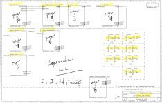
I've watched several repair videos on the Definitive Technology Supercube III. There are some schematics, which were uploaded by the repair video person norcal715 but they are on another website and they aren't allowing new login/user accounts. I believe much of the problems stem from the faulty potentiometers and as the videos revealed. I examined the videos and saw that the Level control pot is an Audio/Logarithmic taper 5k dual, the Frequency pot is a dual B20k Linear, and the Phase pot is a single 50k Audio/Log. You should be able to open the low level board and test the pots.

The files are two high res 13Mg pdf's.
I've copied the pages below as images.
Enjoy 😀
I've copied the pages below as images.
Enjoy 😀
Last edited:
Pre section:
Attachments
-
 Definitive super cube III PRE SECTION - 1.jpg207.3 KB · Views: 335
 -
 Definitive super cube III PRE SECTION - 10.jpg251.5 KB · Views: 324
 -
 Definitive super cube III PRE SECTION - 9.jpg171.7 KB · Views: 310
 -
 Definitive super cube III PRE SECTION - 8.jpg92.7 KB · Views: 305
 -
 Definitive super cube III PRE SECTION - 7.jpg168.6 KB · Views: 293
 -
 Definitive super cube III PRE SECTION - 6.jpg197.5 KB · Views: 301
 -
 Definitive super cube III PRE SECTION - 5.jpg198.7 KB · Views: 285
 -
 Definitive super cube III PRE SECTION - 4.jpg180.4 KB · Views: 289
 -
 Definitive super cube III PRE SECTION - 3.jpg125.2 KB · Views: 271
 -
 Definitive super cube III PRE SECTION - 2.jpg189.6 KB · Views: 323
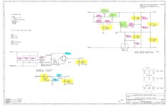
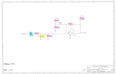
Power section:
Attachments
-
 Definitive super cube III POWER SECTION - 7.jpg147.1 KB · Views: 216
 -
 Definitive super cube III POWER SECTION - 6.jpg287.6 KB · Views: 243
 -
 Definitive super cube III POWER SECTION - 5.jpg238.1 KB · Views: 253
 -
 Definitive super cube III POWER SECTION - 4.jpg92.3 KB · Views: 196
 -
 Definitive super cube III POWER SECTION - 3.jpg99.6 KB · Views: 191
 -
 Definitive super cube III POWER SECTION - 2.jpg200.9 KB · Views: 228
 -
 Definitive super cube III POWER SECTION - 1.jpg217 KB · Views: 201
 -
 Definitive super cube III POWER SECTION - 8.jpg159.5 KB · Views: 211
 -
 Definitive super cube III POWER SECTION - 9.jpg263.1 KB · Views: 197
 -
 Definitive super cube III POWER SECTION - 10.jpg137.3 KB · Views: 192
Repaired one recently. Indeed the three pots were all open circuit. Once the volume pot was changed, it only had output from the LFE input - as the LFE input bypasses the crossover crossover/phase controls.
Once the other two were changed, it was good to go.
Just be careful with these, they are direct mains powered - no isolation from mains to the speaker output. Not that should be a problem, as it would be unusual to be powering an external speaker from the inbuilt amp.
Once the other two were changed, it was good to go.
Just be careful with these, they are direct mains powered - no isolation from mains to the speaker output. Not that should be a problem, as it would be unusual to be powering an external speaker from the inbuilt amp.
I can confirm long ago the manufacture received a bad run of 5K audio taper POTs and before the defect was found these went into production.
The small rivets in the pots that attach the terminals were not properly crimped and due to the vibration inside the subwoofer there was a significant and ongoing failure of the pots with open terminals.
This can result in no signal or full volume with no control depending on what rivet happen to go open in the pot.
If the 20k dual linear pot fails with open rivets this can cause weirdness in the xover frequency control including no signal and/or loud noises again depending on the exact rivet that may go open. The 20K pot came from a different vendor and there were far fewer failures of this pot.
The warning on high voltage is very much needed as these high power amplifiers have about a 350V high current power rail inside.
These are not for the careless to service.
I had fixed that one with replacement preamp and amp boards from eBay, and I can't remember which was actually bad in that one. I ended up selling it for gas money to take a road trip. 😂
I still have my old preamp board however, just sitting around.
Can the pots be tested in-circuit? The ones on my old board seem to react appropriately when tested as such. I have another whole dead SC3 showing up in a week or so that I picked up from Goodwill online. Their description in part reads as follows:
Obviously since I don't have my hands on it yet, I can't do anything more than share that description, but I'm glad some people had responded to this in the meantime and I hope we can get it working.
Those schematics are for the SC3? Some of the description seems to be for the 2, though I'm unsure how much shared design there is between the two.
Thanks for all the information though!
I still have my old preamp board however, just sitting around.
Can the pots be tested in-circuit? The ones on my old board seem to react appropriately when tested as such. I have another whole dead SC3 showing up in a week or so that I picked up from Goodwill online. Their description in part reads as follows:
The subwoofer will power on, HOWEVER it will not make any sound. I tried the Analog Low Level Input, and the High Level Right input, but neither of them made any sound. For parts or repair.
Obviously since I don't have my hands on it yet, I can't do anything more than share that description, but I'm glad some people had responded to this in the meantime and I hope we can get it working.
Those schematics are for the SC3? Some of the description seems to be for the 2, though I'm unsure how much shared design there is between the two.
Thanks for all the information though!
There was a lot of commonalty in both circuits and PCB assemblies between all the super cube models and the later bipolar towers as well.Those schematics are for the SC3? Some of the description seems to be for the 2
The schematics for the low low level board you have does not cover the SC3.
The SC3 design is as I remember very close to the schematics for the SC1, 2, Trinity.
The PCB reference numbers will all be different from a SC3 so that will make it a bit hard to follow.
Be good to find a SC3 low level schematic.
If I remember correctly the SC3 power board was the same board as the other two larger models (SC1, SC2) only with a cut down heat-sink to allow fitting into the very small SC3 box. Kind of like a V8 stuffed into a subcompact car.
This was many products in my past and a very long time ago so my memory is a bit thin I admit.
You can try to test the pots in circuit however it very often gives false results as pushing on the pot pin with a ohm meter or scope probe almost always would cause the pot to work for a bit leading you astray.
If you want to end-up with a reliable unit the best way to go is to simply start by replacing all the pots and then trouble shoot what issues are left.
The low level board is pretty easy to trouble shoot with the exception of the ADA circuits that formats the pulse width modulator to pass the audio signal across the opto coupler.
You can test the low level board without the power board (much easier and safer) by applying 120V to the AC input connector.
First check the power rails.
Then follow the audio path through to the power amplifier interconnect cable.
There you will find the audio riding on a square-ware as a pulse width modulated signal that connects to a opto coupler on the power board.
I think somewhere around 60~80Khz (not sure) is the frequency.
To test the power board you MUST have a a isolation transformer as the power board is hot and directly connected to the power line.
Not using a isolation transformer is asking for destruction of you lab equipment and possibly you singing off as one of the living.
Trouble shooting the power board is a bit tricky and you can easily cause extensive damage rendering it a paper weight.
If you need help with a power board let me know and I will try to provide some hints.
Happy hunting
Last edited:
Yeah we'll see what kind of shape the inbound one is in when it gets here, and hopefully it's the pots cuz voltages above like 20V scare me 😂
I'm used to working on automotive installs where the high voltages are hidden inside metal housings and on the other side of a switching power supply.
I definitely appreciate the help and I'll be back with results once that thing is here and I can get it up on the bench.
I'm used to working on automotive installs where the high voltages are hidden inside metal housings and on the other side of a switching power supply.
I definitely appreciate the help and I'll be back with results once that thing is here and I can get it up on the bench.
Being a bit scared while working on any of the super cube power sections is appropriate in my opinion.cuz voltages above like 20V scare me
They can bite back hard if you are careless... sort of like one of my cats. They are however with care fixable unless the PCB has burned.
Is there anyone in here who diagnoses/fixes the power boards if the low level board checks out? I'm not equipped for that sort of thing at the moment.
Okay so the unit arrived and first tests indicate no audio whatsoever, with both pre-amp boards I have here. The spare pre-amp I use to test, at the very least, produced quiet audio on my last unit, and it produced nothing at all this time around. Yes I know this is me jumping to a conclusion while not having any 'known good' preamp board, it's just gonna be a bit until I get my workbench set up again 😬
@kabaudio if I ship you both the boards, do you have an estimate on repair cost since you mentioned recently repairing some of these?
@kabaudio if I ship you both the boards, do you have an estimate on repair cost since you mentioned recently repairing some of these?
Last edited:
Okay belay my last.
Got all my stuff out of storage and got the bench set up again. Following the "poke it and see what happens" method in NorCal's videos produced sound and/or ground noise at varying levels. So this would indicate power board is okay, which is good.
Does anyone have a source for the parts for the low level board?
- Home
- Amplifiers
- Class D
- Yet Another SuperCube III Failure