A few months ago, there were a few threads that rekindled my interest in radial horns and the Yuichi A-290 in particular. I wanted to make a BEM sim of the A-290 to see it’s directivity and if there were any simple modifications that might result in an improvement. I thought it would be a simple task of transferring the values from the document into a CAD drawing. This turned out not to be the case as the values from the drawings did not create a smooth curve for the horizontal sides. I chose to use a conic curve with a visual best fit between the points in Fusion. The radius dimensions to align the flat section with the fin ends and vertical expansion didn’t quite line up and I decided to fudge it to make it work. The dimensions for the fins produced reasonable curves without any intervention. The original file had the sides being quite flat before curving out as this seemed to match with images of completed horns, I had seen.
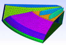
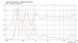
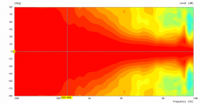
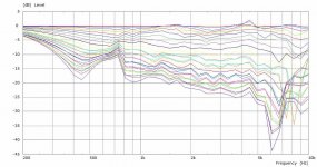
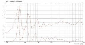
I was able to make a mesh and get a basic simulation going. There were a few problems with the model but overall, the directivity seemed to be reasonably constant in the horizontal as touted. The Radiation Impedance was very spiky and odd looking and looked to me like it could be from simulation errors. I knew @DonVK had simulated some similar horns with @docali so I got in touch with Don to have a look and see if he could offer some advice on what I was seeing. It turned out that there wasn’t too much wrong and that the Rad Imp was reasonably consistent with other horns of the same type.
This sparked off several different simulations to improve the model and look to improve the horn without making it into something completely different. Don made all the model iterations. Ideas on fin placement and number from Kolbrek and Dunker’s book were tried along with asymmetric, golden ratios and some other variations. The results iteratively got better and in tandem docali’s Radial Fin spreadsheets were reworked by him and simulated by Don looking for improvements. The horn’s resulting from docali’s spreadsheets surpassed the best attempts at improving the A-290. As a result of lessons learned there, I took another look at the A-290 documents and reworked the CAD from scratch. I drew three-point arcs based on defined coordinates from the drawings for the side profiles and used the data taken from the excel spreadsheet calculations (included in the A-290 doc) for the vertical curves. This time the fin ends lined up exactly at the end of the flat section and the overall result was much cleaner. The best result for a horn based off Yuichi’s plans used 6 fins with a spacing of 7.5,15,15,15,7.5 degrees. The outer two channels being half fins between the fin and wall.
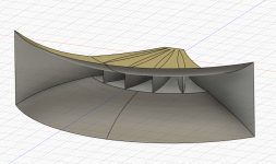
It is still not clear to me if there is a definitive way to produce an exact A-290 as Yuichi intended. What you can find in the attached step and Fusion archives is the blueprint to build either of the versions I created with simulated performance of what to expect.
The V1 is a full 3D solid model, the V2 is a surface model that needs further work to turn it into a full 3D solid for production. Results of selected models to follow in further posts.
Greater simulated performance can be had from similar horns and the information may be released in another thread describing that process or via docali’s sphericalhorns.net website, currently those experiments are still ongoing.
I was able to make a mesh and get a basic simulation going. There were a few problems with the model but overall, the directivity seemed to be reasonably constant in the horizontal as touted. The Radiation Impedance was very spiky and odd looking and looked to me like it could be from simulation errors. I knew @DonVK had simulated some similar horns with @docali so I got in touch with Don to have a look and see if he could offer some advice on what I was seeing. It turned out that there wasn’t too much wrong and that the Rad Imp was reasonably consistent with other horns of the same type.
This sparked off several different simulations to improve the model and look to improve the horn without making it into something completely different. Don made all the model iterations. Ideas on fin placement and number from Kolbrek and Dunker’s book were tried along with asymmetric, golden ratios and some other variations. The results iteratively got better and in tandem docali’s Radial Fin spreadsheets were reworked by him and simulated by Don looking for improvements. The horn’s resulting from docali’s spreadsheets surpassed the best attempts at improving the A-290. As a result of lessons learned there, I took another look at the A-290 documents and reworked the CAD from scratch. I drew three-point arcs based on defined coordinates from the drawings for the side profiles and used the data taken from the excel spreadsheet calculations (included in the A-290 doc) for the vertical curves. This time the fin ends lined up exactly at the end of the flat section and the overall result was much cleaner. The best result for a horn based off Yuichi’s plans used 6 fins with a spacing of 7.5,15,15,15,7.5 degrees. The outer two channels being half fins between the fin and wall.
It is still not clear to me if there is a definitive way to produce an exact A-290 as Yuichi intended. What you can find in the attached step and Fusion archives is the blueprint to build either of the versions I created with simulated performance of what to expect.
The V1 is a full 3D solid model, the V2 is a surface model that needs further work to turn it into a full 3D solid for production. Results of selected models to follow in further posts.
Greater simulated performance can be had from similar horns and the information may be released in another thread describing that process or via docali’s sphericalhorns.net website, currently those experiments are still ongoing.
Attachments
A290V2 -3 Results
Attachments

Thanks for your inspiration to return the abandoned path of making fin horns. The initial attempts together with DonVK were not very successful with symmetric fin arrangement. Then I bought Kolbrek and Dunker’s book and recognized the different fin orientation demonstrated with a 2D simulation which was very promising but there was no "kick-off" to return to this type of horns. So this project was highly welcome to try if the fin horns of the known designs could be improved and to be short the answer is yes.
Without the help and interaction with Don and docali I suspect I would have shelved my efforts much like you guys did earlier on. It was (and still is) nice to have a plan come together and get some great results from collaboration.
I received a PM with a link to a French forum with some scans of Yuichi's book.
https://forums.melaudia.net/showthread.php?tid=8486&page=2
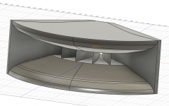
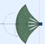
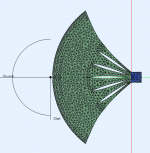
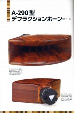
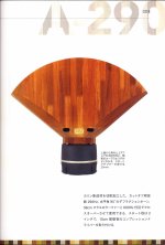
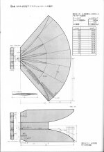
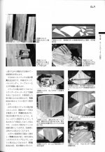
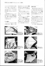
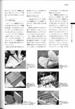
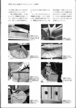
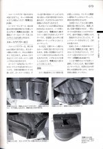
The images in these are quite good and show to me that Yuichi's intent was to have a smooth sidewall curve which looks a lot like the V2 CAD file. I've attached them here for reference with a zip for downloading at the end. The sidewall curve was created from an arc of the throat and mouth end points with centre being the point where the 95 degree straight line crossed the curve as shown in the 4th image.
I received a PM with a link to a French forum with some scans of Yuichi's book.
https://forums.melaudia.net/showthread.php?tid=8486&page=2
The images in these are quite good and show to me that Yuichi's intent was to have a smooth sidewall curve which looks a lot like the V2 CAD file. I've attached them here for reference with a zip for downloading at the end. The sidewall curve was created from an arc of the throat and mouth end points with centre being the point where the 95 degree straight line crossed the curve as shown in the 4th image.
Attachments
-
 Yuichi-Arai-A-290-1-1.jpg314.9 KB · Views: 625
 -
 Yuichi-Arai-A-290-1-2.jpg246.5 KB · Views: 519
 -
 Yuichi-Arai-A-290-2-2.jpg461.7 KB · Views: 538
 -
 Yuichi-Arai-A-290-2-3.jpg431.9 KB · Views: 541
 -
 Yuichi-Arai-A-290-2-4.jpg314.2 KB · Views: 523
 -
 Yuichi-Arai-A-290-2-5.jpg472.1 KB · Views: 415
 -
 Yuichi-Arai-A-290-2-6.jpg484.9 KB · Views: 426
 -
 Yuichi-Arai-A-290-2-7.jpg432.5 KB · Views: 408
 -
 Yuichi-Arai-A-290-2-8.jpg452.7 KB · Views: 407
 -
 Yuichi-Arai-A-290-2-9.jpg426.8 KB · Views: 406
 -
 Yuichi-Arai-A-290-2-10.jpg487.2 KB · Views: 461
 -
 Yuichi-Arai-A-290-2-11.jpg454.8 KB · Views: 475
 -
 Yuichi-Arai-A-290-2-12.jpg467.7 KB · Views: 530
 -
Yuichi-Arai-A-290-2-12.zip9.8 MB · Views: 285
Careful with semi-angle orientation, Kolbrek said also in his book that it's a simple 2D sim and must be validated.
That means it must be try in 3D FEA with a real profile with a end in 4 Pi, on a fins bi-radial horn the side is just another fins so with the semi-angle technique we need a flatter side and it brings problems with mouth diffraction, see-able in 4pi FEA (BEM is less good to see this IMHO).
The result is just a little bit different, tested in FEA and reality, if you want to improve an A290 improve the mouth firstly ^^, you still have sharp 90° edge at the the very end of your profile.
I can search the measurement but as the project has been considered as not very successfully ^^, some years ago, so where is the files now...
Basically the change on the the side make the horizontal edge more impacting, meaning that in real application 4pi it's problematic :
On a biradial we generally want that the side finish inside the horizontal circle (inside the cylinder), and we also have to take some space inside it for a complete return like you can do with an ATH4 R-OSSE.
The result was an bigger impact of the horizontal mouth diffraction so an off axis accident in relatively high frequencies, but as it's was not better we follow another direction and more FEA driven but an easy way is just to round it like with R-OSSE or JMLC profiles (yes it will be bigger).
You can look at what JMS does: https://www.jmf-audio.com/references
But it's even not very good comparing to a regular rounded profile, they does this for don't take to much space and may be for design purpose.
It's also more complex/time consuming to mix + and - profile on a wood CNC.
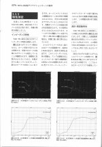
I finds some measurement, keep in mind that I wasn't the guy that measure it, the method was not exactly the same between the two horn, but well it give an idea.
So, Arai 1.5 (not a real one recalculated, it's a down-scaled) :

Almost the same in semi-angle 4 fins, it cannot be the same because side is a bit different in semi angle technique :

There still be only 4 fins here, more fins you have more you push the finger response (white mark between 2 and 6khz) upper.
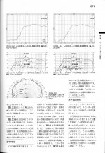
So if we use 8 fins and slightly better rounded (also better measurement context apparently) the accident I describe is still present, every horns have midrange narrowing (1khz) but easier to see in good context and with a finger response push higher :

So my advice, stay like Arai does and round as you can as JMLC or R-OSSE does.
There is way to do better than this but with FEA and starting from a blank page.
Using fins bring also a different energy distribution, on a OS for ex the +/-15 is on the 0° then the 30° is a step bellow, for an horn with fins this behavior is push to +/-30° close to the 0°.
So, Arai 1.5 (not a real one recalculated, it's a down-scaled) :
Almost the same in semi-angle 4 fins, it cannot be the same because side is a bit different in semi angle technique :
There still be only 4 fins here, more fins you have more you push the finger response (white mark between 2 and 6khz) upper.
So if we use 8 fins and slightly better rounded (also better measurement context apparently) the accident I describe is still present, every horns have midrange narrowing (1khz) but easier to see in good context and with a finger response push higher :
So my advice, stay like Arai does and round as you can as JMLC or R-OSSE does.
There is way to do better than this but with FEA and starting from a blank page.
Using fins bring also a different energy distribution, on a OS for ex the +/-15 is on the 0° then the 30° is a step bellow, for an horn with fins this behavior is push to +/-30° close to the 0°.
Theirs were 2D and these shown here are 3D.Careful with semi-angle orientation, Kolbrek said also in his book that it's a simple 2D sim and must be validated.
I don't have access to FEA or FEM so I use what I have. ABEC/AKABAK has been shown time and again to be remarkably close in simulation to the directivity that results in real life. What's left that isn't accounted for doesn't seem to invalidate the data in any significant way.That means it must be try in 3D FEA with a real profile with a end in 4 Pi, on a fins bi-radial horn the side is just another fins so with the semi-angle technique we need a flatter side and it brings problems with mouth diffraction, see-able in 4pi FEA (BEM is less good to see this IMHO).
The full simulated mesh and simplified rear isn't shown here, it is a time saving feature as the meshes get unreasonably large adding in the edge roundovers and increasing mesh resolution. Many things were tried that are not presented here. Enough tests of alternative arrangements were made to feel confident in these.you still have sharp 90° edge at the the very end of your profile.
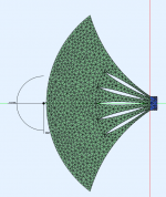
My interpretation of how I would build a similar horn looks like this
I don't remember if that was done with these, it was on other designs I would have to dig back through and look.Could we see a with/without fins comparison? I'm interested on the effect they have on the horizontal polar response
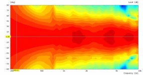
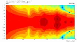
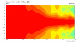
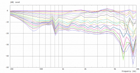
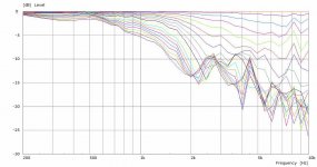
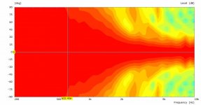
They don't have too but most do, the horizontal polar of the CAD drawing above, it has fins not shown in the renderthe accident I describe is still present, every horns have midrange narrowing (1khz)
Hi @fluid, did you ever get around to making the full 3D solid model of the V2 horn?The V1 is a full 3D solid model, the V2 is a surface model that needs further work to turn it into a full 3D solid for production. Results of selected models to follow in further posts.
Greater simulated performance can be had from similar horns and the information may be released in another thread describing that process or via docali’s sphericalhorns.net website, currently those experiments are still ongoing.
Is the rendering below of the V2 horn? No fins?
I have been tempted to order a pair of Yuichi A290 horns for a while, but these would be even better
")
The simulation results give no clear answer to this as the number of elements for the BEM sim was already very high to solve within a reasonable time and computer resources. HF results could become better with higher resolution.You have a problem at 10khz no ?
The next point is that this sim sfair had a non-optimized adapter shape. We did some investigation with respect to wave front shaping (by using special shaped adapter geometry) which improves HF significantly. But you have to be aware that we have a 2in exit and the slot width is not really optimal to
control HF dispersion.
Btw, the shape was optimized to largely avoid any midrange narrow in the hrz plane.
- Home
- Loudspeakers
- Multi-Way
- Yuichi A-290 CAD files, modifications and BEM simulation results