A search for:
Q608 JL 500
Would have lead you to the following thread:
http://www.diyaudio.com/forums/car-audio/121433-jl-500-1-smd-transistors.html#post1485563
Q608 JL 500
Would have lead you to the following thread:
http://www.diyaudio.com/forums/car-audio/121433-jl-500-1-smd-transistors.html#post1485563
Hello Guys,
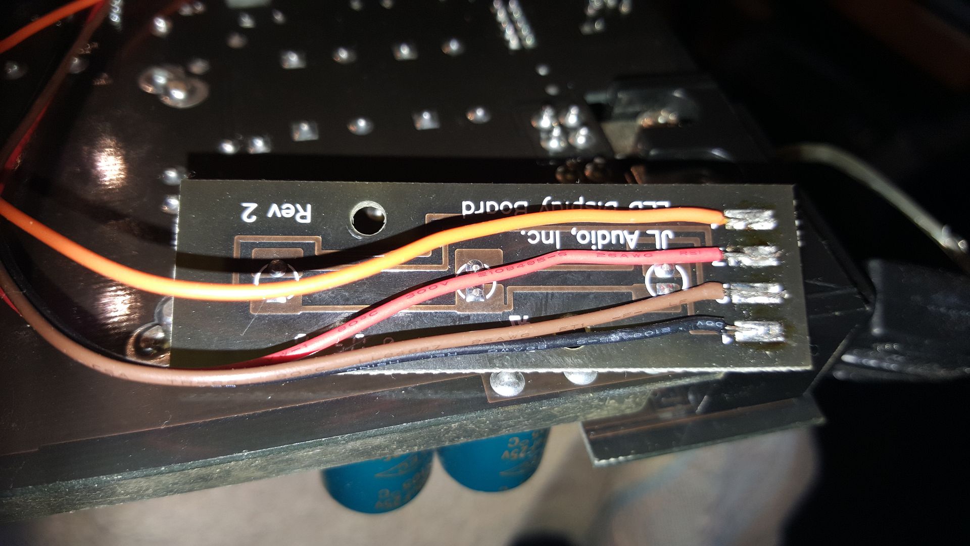
I've replaced with original IRFZ44N fets and gate resistors on the power supply side. Perry, can I test the transistors Q608 thru Q611 in circuit or should I lift them? In the process of moving the amp around the leads for the led panel have come off. If any one could supply a photo of the wires running to the panel so I can verify the color and location to re-solder them? It would be greatly appreciated.
I've replaced with original IRFZ44N fets and gate resistors on the power supply side. Perry, can I test the transistors Q608 thru Q611 in circuit or should I lift them? In the process of moving the amp around the leads for the led panel have come off. If any one could supply a photo of the wires running to the panel so I can verify the color and location to re-solder them? It would be greatly appreciated.
Attachments
![20150810_133616[1].jpg](/community/data/attachments/468/468279-074753f6e1046681ebc1e961b7bd4901.jpg?hash=B0dT9uEEZo)
![20150810_133943[1].jpg](/community/data/attachments/444/444247-c86042280d2028fad70d7b306efa889a.jpg?hash=yGBCKA0gKP)
Last edited:
Testing them in the circuit may not be easy but the traces are very small so I wouldn't recommend trying to remove them. It's generally better to check the drive signal before installing the FETs. Since they're already in the circuit, power it up through a 10 amp fuse to see if it draws excessive current. This should be done with all transistors clamped to the heatsink.
In the future, wrap the LED board and wires with tape to prevent stressing the solder connections. It's good to apply a line of adhesive like Goop or E6000 just beyond the solder connections to protect the wiring in the future. I'll see if I can find a photo.
In the future, wrap the LED board and wires with tape to prevent stressing the solder connections. It's good to apply a line of adhesive like Goop or E6000 just beyond the solder connections to protect the wiring in the future. I'll see if I can find a photo.

Very well
Thank you Perry. I made quick use of the photo 🙂
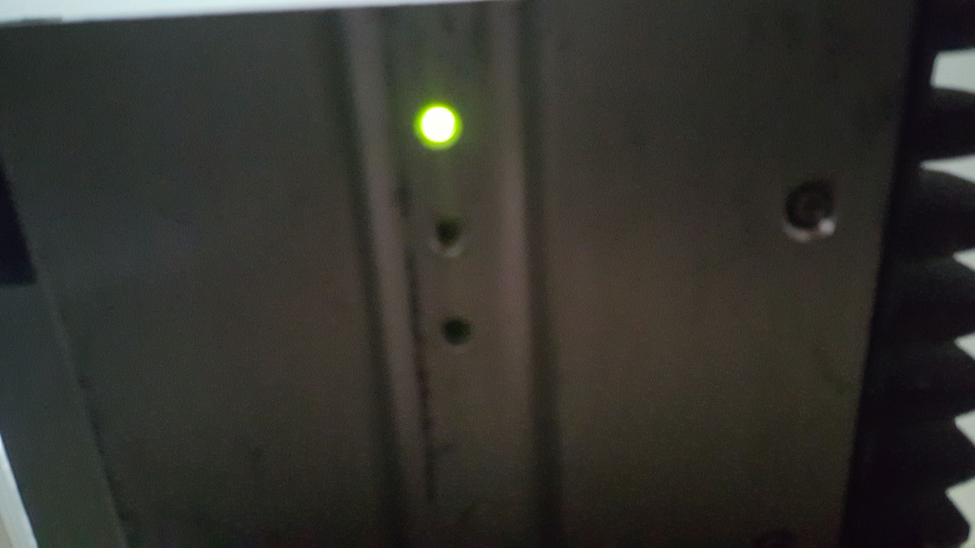
Buttoned it back up and tested it with a 5 amp fuse I had at hand. Got the green light and no smoke or heat anywhere that I can detect thus far. Guess Ill check for some audio...😱

Thank you Perry. I made quick use of the photo 🙂
Buttoned it back up and tested it with a 5 amp fuse I had at hand. Got the green light and no smoke or heat anywhere that I can detect thus far. Guess Ill check for some audio...😱
Last edited:
Well we have clean audio  . Sounds good. My only nagging concern is the heat sensor or thermistor located beside the ps fet bank in the second photo of post #25. Seems like it should be something to hold this thing against the chassis for proper thermal exchange. Perhaps I misplaced a clip?
Thanks for all the help provided and recieved here on Diy Audio 🙂
. Sounds good. My only nagging concern is the heat sensor or thermistor located beside the ps fet bank in the second photo of post #25. Seems like it should be something to hold this thing against the chassis for proper thermal exchange. Perhaps I misplaced a clip? Thanks for all the help provided and recieved here on Diy Audio 🙂
Last edited:
You're missing a clip. There should be one more like the others that clamps the rectifier and the thermal. Don't run the amp hard with the rectifier loose.
Seems like something goes between the rectifier and chassis as the way the leads are situated it doesn't just fit flat up against the chassis like the fets did. Im not in a place where I can take a photo of it till later this morning. I will as soon as possible if you aren't familiar with what I'm talking about. I didn't drive the amp hard as It seemed an ill advised idea with the thermal protection and rectifier not touching the chassis. If I cannot find the clip can the rectifier has own separate heat sink if I cant find one? Im a certified cnc and manual machinist as well so I have already contemplated ways around this clip issue if I cannot source the clip. Id sure hate to have to do that though..🙁
Thanks again Perry.
Hugh
Thanks again Perry.
Hugh
Last edited:
Not on this amp. It should lay flat. If it doesn't, the leads aren't bent properly. The center leg has to be bent out so the rectifier can lay flat.
You can use the following clips if you cannot find a replacement.
http://www.futureelectronics.com/en...nt/thermal-tapes/Pages/7503311-4525.aspx?IM=0
Being able to do various types of metalwork will come in handy for amp repair but it's not necessary here.
You can use the following clips if you cannot find a replacement.
http://www.futureelectronics.com/en...nt/thermal-tapes/Pages/7503311-4525.aspx?IM=0
Being able to do various types of metalwork will come in handy for amp repair but it's not necessary here.
Attachments

Last edited:
Thank you,
Is that a piece of thermal tape in between? Not trying to bug but do u have a photo showing me the mount further back? I need to see what the entire clip looks like.
I have several amps I'm repairing here so It may have been placed in the wrong bag for another amp. I try my best to keep up with everything but I have a good many projects going on right now.
The amp in the photo is the newer version and uses a large clamp with screws. The photo shows the center leg bent out so that it goes straight down into the offset hole. If the leg is left straight (with no bend), the transistor won't lay flat.
Most JL amps use mica insulators (that's what's behind the transistors).
Most JL amps use mica insulators (that's what's behind the transistors).
Not on this amp. It should lay flat. If it doesn't, the leads aren't bent properly. The center leg has to be bent out so the rectifier can lay flat.
You can use the following clips if you cannot find a replacement.
4525 | TO-220 Package 19 x 9 mm Heat Sink Clip | AAVID THERMALLOY - Future Electronics
Being able to do various types of metalwork will come in handy for amp repair but it's not necessary here.
About machining.....
Yes I have a soundstream reference 500 that would be a real challenge to rebuild .Its burned horribly on the in ps side. Im thinking to cut away the bad board section and remake the pcb section on the mill and patch it in. I know it sounds silly but Im interested in the challenge vs scraping it at the recycling center . It may still end up there 😱
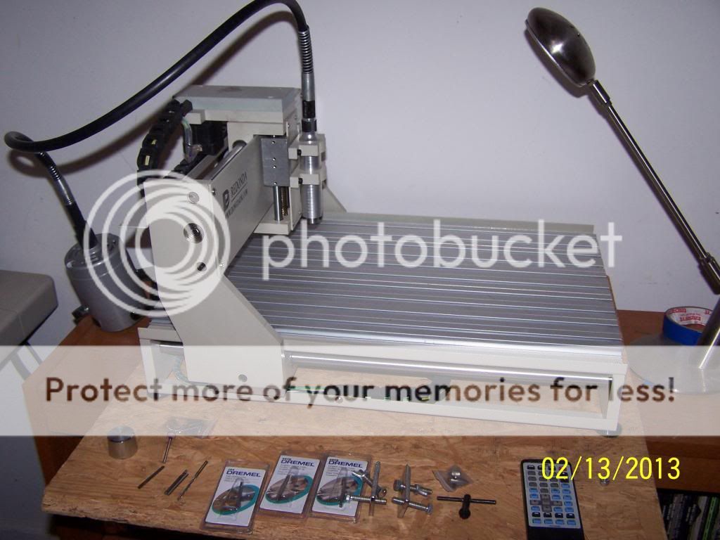
Here is a photo of my pcb mill . It has a work area that is suitable for doing a decent sized board . It wont do a big board like a series 6 or 7 colossus but a board for an amp like this it could pull it off. I have a nice Class A B design Id like to build from the bottom up. Im drawing in dip trace and using copper cam to generate the G code.
I will post start and post these things once I get all these amps I have here troubleshot and repaired. Taking it one amp at a time......

Thanks again for all your help
Last edited:
I redondak ts3040 I think Ill have to check it for sure when I get back to the shop.
Aluminum yes mild steel I wouldnt try. Its a dedicated pcb mill the motor is only 1/4 hp. I have much larger machines on the way for such things. Looking to maybe purchase a HAAS mini mill sometime in October. I looked at a Tormack but I dont think it will hold the numbers like the Haas would for the other work I have for it outside of audio repair.
Aluminum yes mild steel I wouldnt try. Its a dedicated pcb mill the motor is only 1/4 hp. I have much larger machines on the way for such things. Looking to maybe purchase a HAAS mini mill sometime in October. I looked at a Tormack but I dont think it will hold the numbers like the Haas would for the other work I have for it outside of audio repair.
Last edited:
I wanted a Sherline but never could justify it.
For small holes, you can use JB Weld to fill and hardwire the traces. For larger areas, (for most people) it would be better to lay it out in something like Eagle and have the section of the board printed by a boardhouse like PCBFabExpress.
For small holes, you can use JB Weld to fill and hardwire the traces. For larger areas, (for most people) it would be better to lay it out in something like Eagle and have the section of the board printed by a boardhouse like PCBFabExpress.
Attachments

Hi Perry,
I dont know ,what the Sherline cost its work area or abilities but the Redondak was around grand. With the skills youve exhibited you certainly seem justifiably worth that 🙂 The copper cam, art cam and mach3 were included with the machine so that was nice to get started. I'm not a big fan of Mach as of yet but I haven't really had that much exposure to it. I was trained on Mastercam which is a much more elaborate user friendly cam app for me at this time but quite naturally you wont get a free seat of it with a machine 😱
BTW thanks for the invaluable link to the clips even if I find the original. Does this supplier also provide chassis extrusions ?
Hugh
Last edited:
What type of extrusions?
Chassis material that can be cut to the length you need to house a pcb for prototype amplifiers.
I also found the clip, so I guess I can move on to the next repair project now.

Thank you again for your invaluable assistance.
Hugh
Last edited:
- Status
- Not open for further replies.
- Home
- General Interest
- Car Audio
- JL Audio 500/1 Rev. 10