The whole MQA thing feels really fishy.
Which USB interfaces? ASIO or WMA? (How many ways can we make recording music hard?)
Audacity does not support ASIO officially because the underlying open source library they use does not. ARTA works fine with several external ASIO devices as do the demo versions of several not free DAW's. I find the DAW's far too busy with too many tools I have no interest in. I'll check ocenaudio this weekend, they went to more than a little effort to make it look like CoolEdit/Audition. At the moment I don't have any up to date desktop machines.
BTW the CoolEdit/Audacity SDK does have a small prime factor FFT (so 48/96k FFT's are OK) and one could write some fairly nice scientific research tools on top of its memory management and user interface, I know Angelo Farina sells some very interesting plugins.
Last edited:
Microsoft significantly improved the audio stack in Windows 10, but most applications are using older APIs still. For "measurement" tools, WASAPI exclusive mode should probably be what is used on Windows.
foobar2000: Components Repository - WASAPI output support
https://msdn.microsoft.com/en-us/wi...-audio#audio_stack_improvements_in_windows_10
foobar2000: Components Repository - WASAPI output support
https://msdn.microsoft.com/en-us/wi...-audio#audio_stack_improvements_in_windows_10
Microsoft significantly improved the audio stack in Windows 10, but most applications are using older APIs still. For "measurement" tools, WASAPI exclusive mode should probably be what is used on Windows.
foobar2000: Components Repository - WASAPI output support
https://msdn.microsoft.com/en-us/wi...-audio#audio_stack_improvements_in_windows_10
On my list to explore so far Audacity had WASAPI greyed out on the cards that worked fine with ARTA. Two of my devices are very recent purchases, you are correct several other devices I have are just too old and no longer supported. Your link says output not sure about recording. The frustrating thing is that when I wrote my first LA article I used an Maudio USB DUO that worked fine at 24/48 in full duplex with two instances of CoolEdit, 10yr. ago.
Last edited:
John Atkinson seemed to refer to this "paper" as the starting point for the dispersion story: http://www.aes.org/tmpFiles/elib/20161111/18046.pdf It really felt weak on content and pretty marketing oriented. Is all I have found on the subject so far. However it suggests a combination of antialiasing filter and reconstruction filter (to remove group delay?) is the trick.
John Atkinson seemed to refer to this "paper" as the starting point for the dispersion story: http://www.aes.org/tmpFiles/elib/20161111/18046.pdf It really felt weak on content and pretty marketing oriented. Is all I have found on the subject so far. However it suggests a combination of antialiasing filter and reconstruction filter (to remove group delay?) is the trick.
It gets weak soon, is this really about Gibb's effect, etc? They always talk about pre-ringing but there are no large scale steps in most source material. I would like to see an energy/time plot of some real sources presented. At least one thing is clear he does state rigidly lossless is not important not always clear from other stuff I have read.
Last edited:
On my list to explore so far Audacity had WASAPI greyed out on the cards that worked fine with ARTA. Two of my devices are very recent purchases, you are correct several other devices I have are just too old and no longer supported. Your link says output not sure about recording. The frustrating thing is that when I wrote my first LA article I used an Maudio USB DUO that worked fine at 24/48 in full duplex with two instances of CoolEdit, 10yr. ago.
I use an EMU 1820m which I had to replace all the electrolytic caps on. It gets hot inside with all those AK5394 ADCs and the caps for the switcher are cheap Chinese stuff not up to the ripple current.
Works fine in Windows 10 if you mind the quirks of their PatchMix software. I actually really like it, a shame it needs a PCI card to interface (not PCIe) and they are discontinued. It supports a ton of simultaneous ASIO streams. I am still using an Intel X58 chipset motherboard that still has a PCI slot for that reason. Have a 6-core Xeon overclocked to 4.4GHz in it though so it is still competitive performance wise.
"CD smears timing for 4 milliseconds"
Wow, that is some great stuff.
Yepp - must be important...
"Moreover, the gestalt of listening to MQA is fundamentally different than, for example, listening to different examples of DACs, or even comparing CD-quality audio to so-called “high-resolution” digital audio with high sample rates and long word lengths. MQA is so much better sounding than any other digital that it’s like hitting the “reset” button on an entire branch of audio technology."
http://www.theabsolutesound.com/buyers_guides/37/download/zip/
//
Is all I have found on the subject so far. However it suggests a combination of antialiasing filter and reconstruction filter (to remove group delay?) is the trick.
Had one of those head scratch moments this morning. I remembered several years ago recreating the Earthworks white paper on measuring microphone impulse response with a spark discharge. They gave few details, so I had to do my own research. The solution is complex using some non-linear acoustics because the resulting "inpulse" is actually a shock wave. The short story was that an ordinary sound card could capture it and with very little correction from the theory the response matched a calibration curve derived by standard techniques out to 20kHz, no energy "smeared" 4ms, it would have gone off the screen, so again I don't get what they are referring to. BTW your link had a discussion section, other engineers are equally baffled.
Several years later someone kindly sent me a link to an MIT thesis where the exact solution was given using Bessel functions it only made things more clear at the frequency extreme.
Last edited:
Hello,
JensH,
My FPGA board ordered at Mouser is delayed and will only arrive in early December.
I'm a little bit impatient to play with...
The averaging filter has not a flat response, i lost about 6dB at 96k for SR=192k.
You can look below the frequency plot response of the internal filter below (from LT datasheet).
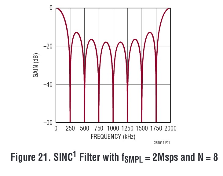
Frex
Yes, I have seen that. It looks like the usual SINC filter response. That's why I suggested to use a different filter. Making the filter selectable sounds like a good idea.
You write that you loose about 6dB at 96k. From the curse above I would have though that it would be more like 3dB, but I haven't checked the mathematical number.
On another topic: In the initial description you write that you designed a new front-end based on the MAX44206. You seem to get very good results with that front-end. Unfortunately Maxim says that the MAX44206 is "Not Recommended for New Designs", which could give some worries about the future availability of the chip. I have not been able to find a replacement from Maxim.
Do you know of any replacement with the same performance?
Sure about that ? It's a pretty new part, don't see it say NRND, it's actually a pretty impressive part....
At least that's what Maxim states here:
https://www.maximintegrated.com/en/products/analog/amplifiers/MAX44206.html/tb_tab0
https://www.maximintegrated.com/en/products/analog/amplifiers/MAX44206.html/tb_tab0
At least that's what Maxim states here:
https://www.maximintegrated.com/en/products/analog/amplifiers/MAX44206.html/tb_tab0
I wonder if they ship a demo card that measures -152dB 3rd at 10K.🙄
Hello,
According to their product status code, we can read this :
So, the product is available.
I have already seen this status, and even if Maxim say "no worry" it seem to be wise to have a second source.
Very high performance fully differential buffers are rare.
In order to find another way, i have ordered some MAX9632 OPAMP, because they
seem to be one of better parts available (THD level, input noise...).
I will try soon to build another front-end with this.
(I look also on the Analog Devices ADA4898-1)
JensH, i got about -6dB@96k because my sampling frequency is 1536kHz (not 2MHz like in datasheet graph),
and because the MAX44206 is also a 2nd order low pass filter that add -3dB@96kHz.
So, you are right about a -3dB attenuation of the digital filter itself.
Frex
According to their product status code, we can read this :
NRND
Not recommended for new designs. The product is in production and available, and is not scheduled to be discontinued.
We do not recommend using this product for new designs because there is a better or more economical alternative,
or because demand for the product is decreasing. We list recommended replacements when possible.
So, the product is available.
I have already seen this status, and even if Maxim say "no worry" it seem to be wise to have a second source.
Very high performance fully differential buffers are rare.
In order to find another way, i have ordered some MAX9632 OPAMP, because they
seem to be one of better parts available (THD level, input noise...).
I will try soon to build another front-end with this.
(I look also on the Analog Devices ADA4898-1)
JensH, i got about -6dB@96k because my sampling frequency is 1536kHz (not 2MHz like in datasheet graph),
and because the MAX44206 is also a 2nd order low pass filter that add -3dB@96kHz.
So, you are right about a -3dB attenuation of the digital filter itself.
Frex
Can you share more? Perhaps on a different thread? I would like to duplicate the results of using a spark discharge.Had one of those head scratch moments this morning. I remembered several years ago recreating the Earthworks white paper on measuring microphone impulse response with a spark discharge. They gave few details, so I had to do my own research. The solution is complex using some non-linear acoustics because the resulting "inpulse" is actually a shock wave. The short story was that an ordinary sound card could capture it and with very little correction from the theory the response matched a calibration curve derived by standard techniques out to 20kHz, no energy "smeared" 4ms, it would have gone off the screen, so again I don't get what they are referring to. BTW your link had a discussion section, other engineers are equally baffled.
Several years later someone kindly sent me a link to an MIT thesis where the exact solution was given using Bessel functions it only made things more clear at the frequency extreme.
Sent from my LG-H811 using Tapatalk
Can you share more? Perhaps on a different thread? I would like to duplicate the results of using a spark discharge.
Sent from my LG-H811 using Tapatalk
Let me check my archives, I'm sure I have it all somewhere.
New ADC box with FPGA board
Hello,
I advance in the project development.
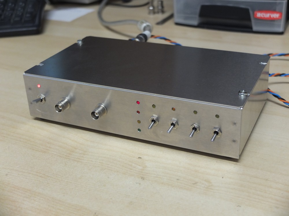
I've received the FPGA EVM some weeks ago and started to build a new box for them.
I added also some I/O connectors and some switches and leds.
I used an aluminum enclosure from Hammond.
The boards are now installed and i made some first tests with the original PLD software today with success (no filter).
I can work now to play with the CPLD EVM...
Some pictures below of the new box.
LTC2380-24 ADC box V2 - Front view.
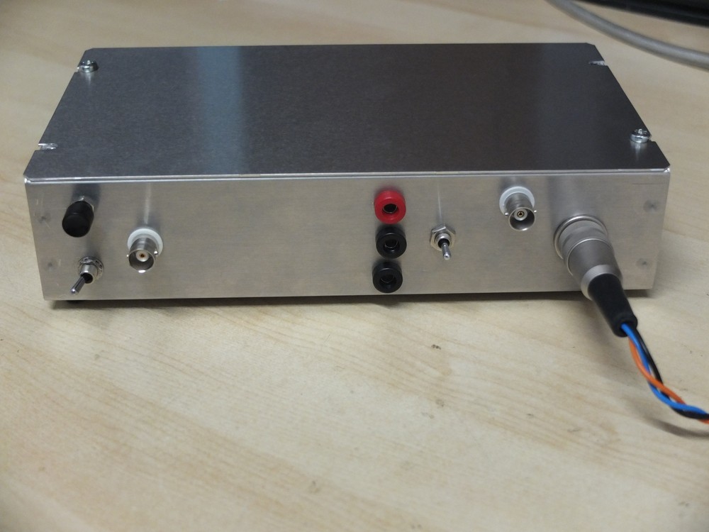
LTC2380-24 ADC box V2 - Rear view.
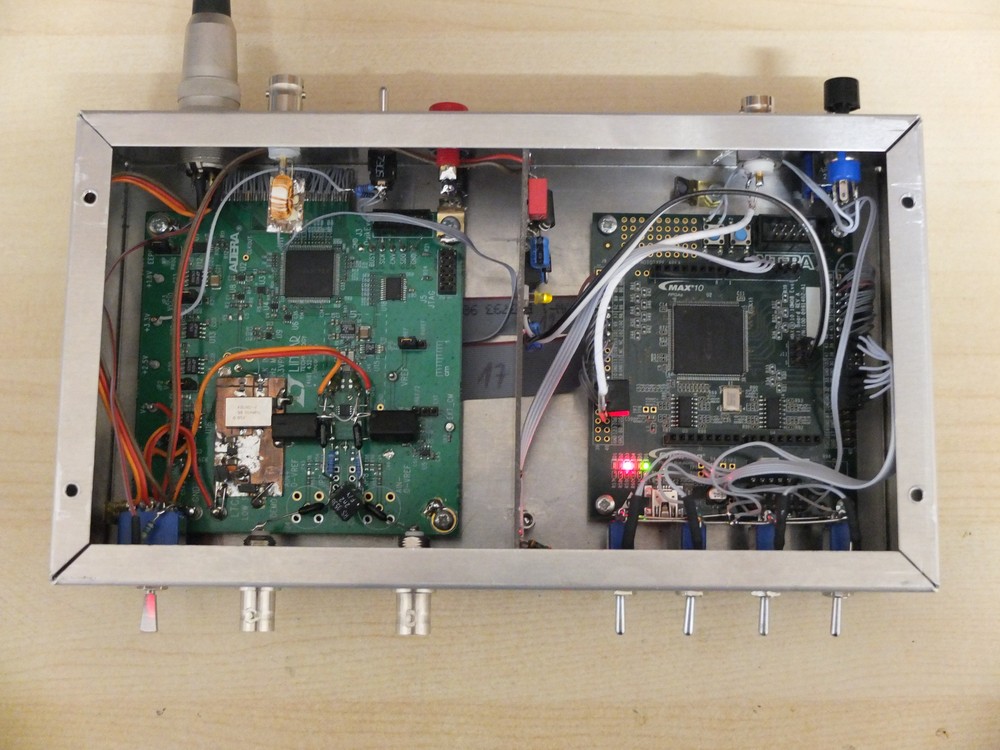
LTC2380-24 ADC box V2 - Internal view.
I plan to use the multicolors leds to indicate the output sampling rate,
and the four front switches to select filter type.
The ADC board send the full 24 bits data of the ADC to avoid high bit rate.
Some others signals like clock and control signals are also sent.
There is two SPDIF output, one coming directly from the ADC EVM,
and another coming from the EVM (digital processed output).
The rear right switch and the push-button allow to select on the fly
the internal FPGA software we want to load.
So now i need to work a little to write the software...
To follow...
Frex
Hello,
I advance in the project development.
I've received the FPGA EVM some weeks ago and started to build a new box for them.
I added also some I/O connectors and some switches and leds.
I used an aluminum enclosure from Hammond.
The boards are now installed and i made some first tests with the original PLD software today with success (no filter).
I can work now to play with the CPLD EVM...
Some pictures below of the new box.
LTC2380-24 ADC box V2 - Front view.
LTC2380-24 ADC box V2 - Rear view.
LTC2380-24 ADC box V2 - Internal view.
I plan to use the multicolors leds to indicate the output sampling rate,
and the four front switches to select filter type.
The ADC board send the full 24 bits data of the ADC to avoid high bit rate.
Some others signals like clock and control signals are also sent.
There is two SPDIF output, one coming directly from the ADC EVM,
and another coming from the EVM (digital processed output).
The rear right switch and the push-button allow to select on the fly
the internal FPGA software we want to load.
So now i need to work a little to write the software...
To follow...
Frex
Hello all,
I worked on the FPGA board these days, i finally successfully made my first FIR
filter worked in the signal path.
For now, the FIR is implemented with 192kHz sampling rate input stream, not the full rate (1.6Msps) i need to make decimation for anti-alias purpose.
I need to modify the first CPDL of the LTC2380 EVM to send data at that rate.
Anyway, this step allow me to check if the FIR filter work properly as expected.
The answer is yes, the resulting Bode plot i've done with Arta is fairly near the theoretical response given from GNU Octave.
This test FIR have the following parameters :
Low Pass, Fc=11kHz, Fstop=15kHz//96kHz, Attenuation =-100dB, Ripple = 0.4dB, 175 Taps.
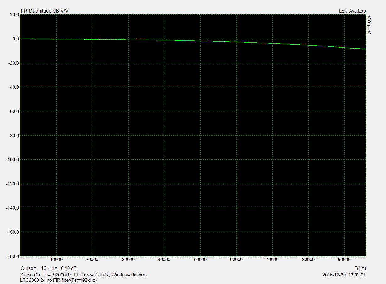
First, when filter is bypassed the frequency response looks like this (active low-pass filter only):
An now the frequency response plot when FIR is active (real measurement, not simulation !) :
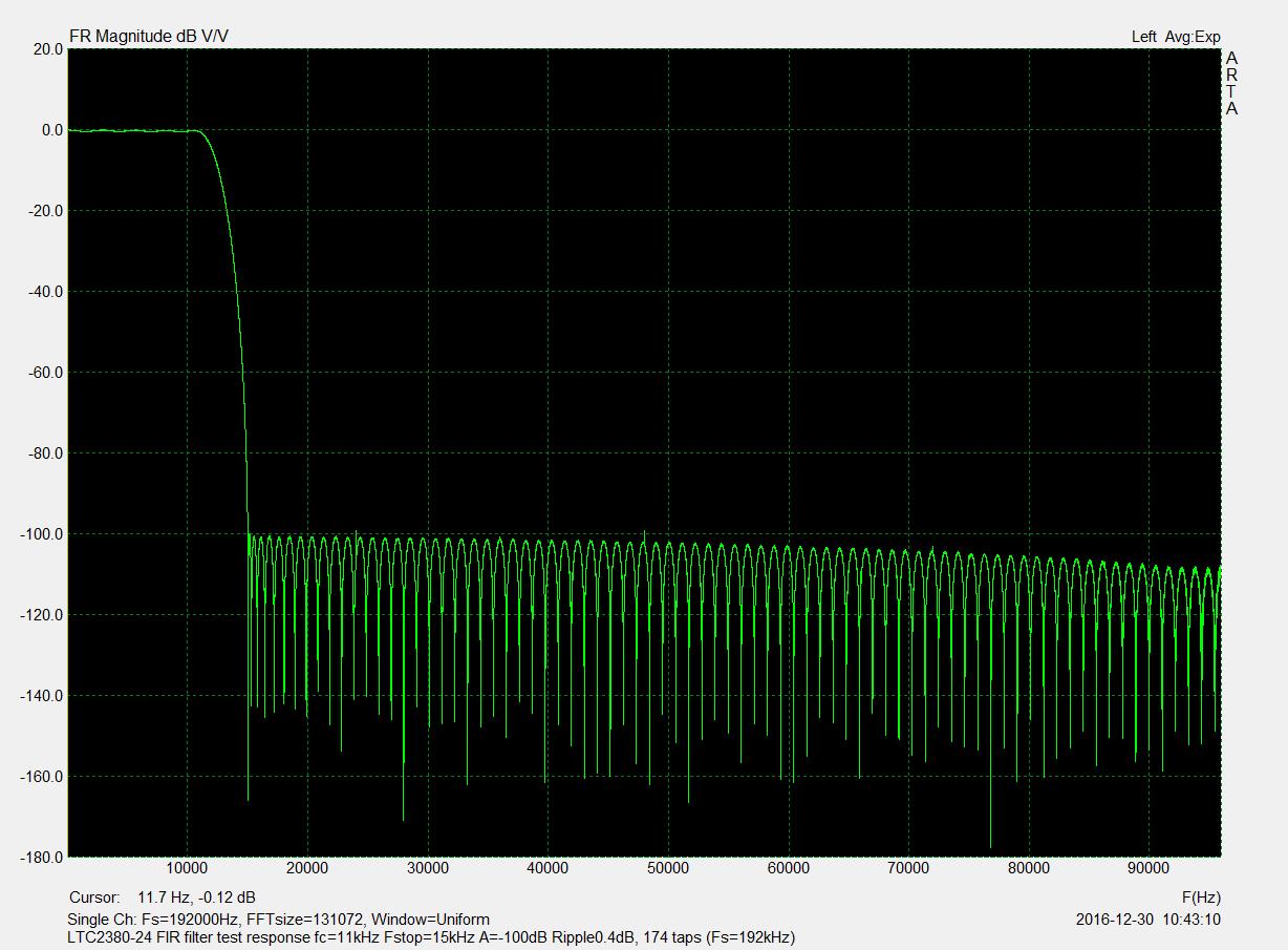
All measurements are made from SPDIF stream of the box and captured with Arta.
I've also captured time domain data to show the 1kHz square wave response with and
without the filter. The results is below :
Without FIR filter :
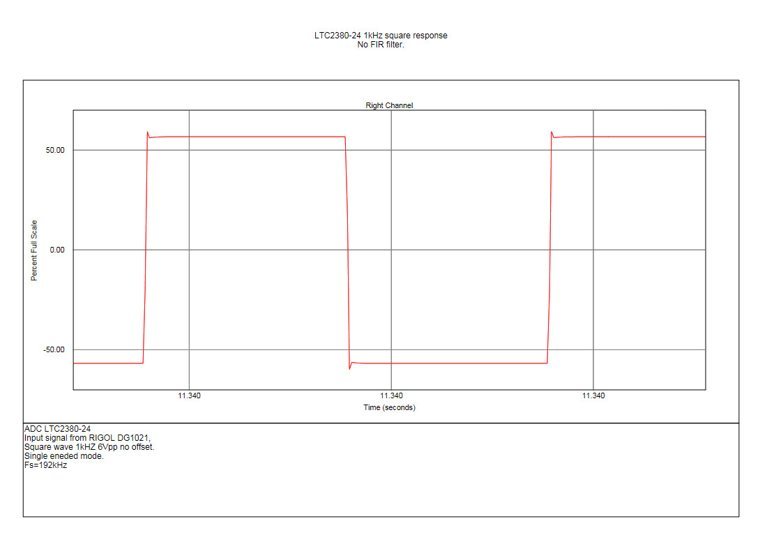
As we see, the step response is very sharp (SAR ADC).
With FIR filter :
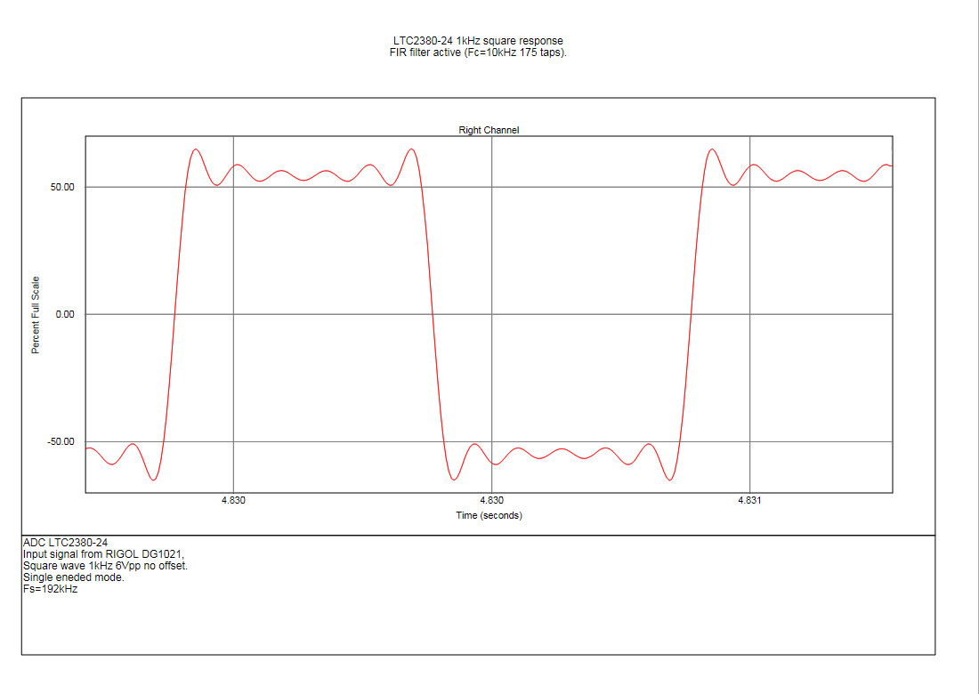
We can show here the typical symmetric time response of the RIF filter.
Same as books !
Of course these results only allow to show that FIR implementation work well in that CPLD.
And this, even with the very sharp roll-off of the filter with 175 taps (or coefficients) the
CPLD still under 20% full.
So, i still continue to work on sending full rate data (1.6Msps) to FPGA board and many others functionality.
I made some work also on another point of the design, sending the data stream using USB link.
We share with Mogens (from here) to find a way on this solution. He's design skill could help a lot.
Adding a USB interface supporting 192kHz (and even more) sampling rate from the FPGA board
will allow to avoid the use of sound card. The analyzer would be seen as an external sound card.
For this point i would avoid to use proprietary solution.
I look also about the use of the SDR-widget board (from Georges Boudreau) , that seem to do the job.
The original design support the AK5394A ADC as master source and send 192kHz data on USB,
so i really think that could work well on my design with minimum work.
The design is non longer sale, but design files are available and if necessary i will order a batch
of the PCB, maybe a small PCB group-buy if others DIYers are interested...
Some DIYers ask me for sharing the CPLD software, for now it is really under development
so i will not publish now. When the project would be ready for a group buy all hardware and software
will be open-sourced. I don't know exactly in wich form, i must take info about that...
For now i use only an "exploded" solution with the LT and Altera EVM, so the final software
will change a lot for a final real PCB with all in one.
Anyway, for DIYers that have purchased the Linear Tech DC2289A-A EVM and would play with,
they can ask me the source code of the EPM570 CPLD that allow to send SPDIF data of averaged sample,
i will send them.
Of course too, happy holidays everybody !
Frex
I worked on the FPGA board these days, i finally successfully made my first FIR
filter worked in the signal path.
For now, the FIR is implemented with 192kHz sampling rate input stream, not the full rate (1.6Msps) i need to make decimation for anti-alias purpose.
I need to modify the first CPDL of the LTC2380 EVM to send data at that rate.
Anyway, this step allow me to check if the FIR filter work properly as expected.
The answer is yes, the resulting Bode plot i've done with Arta is fairly near the theoretical response given from GNU Octave.
This test FIR have the following parameters :
Low Pass, Fc=11kHz, Fstop=15kHz//96kHz, Attenuation =-100dB, Ripple = 0.4dB, 175 Taps.
First, when filter is bypassed the frequency response looks like this (active low-pass filter only):
An now the frequency response plot when FIR is active (real measurement, not simulation !) :
All measurements are made from SPDIF stream of the box and captured with Arta.
I've also captured time domain data to show the 1kHz square wave response with and
without the filter. The results is below :
Without FIR filter :
As we see, the step response is very sharp (SAR ADC).
With FIR filter :
We can show here the typical symmetric time response of the RIF filter.
Same as books !
Of course these results only allow to show that FIR implementation work well in that CPLD.
And this, even with the very sharp roll-off of the filter with 175 taps (or coefficients) the
CPLD still under 20% full.
So, i still continue to work on sending full rate data (1.6Msps) to FPGA board and many others functionality.
I made some work also on another point of the design, sending the data stream using USB link.
We share with Mogens (from here) to find a way on this solution. He's design skill could help a lot.
Adding a USB interface supporting 192kHz (and even more) sampling rate from the FPGA board
will allow to avoid the use of sound card. The analyzer would be seen as an external sound card.
For this point i would avoid to use proprietary solution.
I look also about the use of the SDR-widget board (from Georges Boudreau) , that seem to do the job.
The original design support the AK5394A ADC as master source and send 192kHz data on USB,
so i really think that could work well on my design with minimum work.
The design is non longer sale, but design files are available and if necessary i will order a batch
of the PCB, maybe a small PCB group-buy if others DIYers are interested...
Some DIYers ask me for sharing the CPLD software, for now it is really under development
so i will not publish now. When the project would be ready for a group buy all hardware and software
will be open-sourced. I don't know exactly in wich form, i must take info about that...
For now i use only an "exploded" solution with the LT and Altera EVM, so the final software
will change a lot for a final real PCB with all in one.
Anyway, for DIYers that have purchased the Linear Tech DC2289A-A EVM and would play with,
they can ask me the source code of the EPM570 CPLD that allow to send SPDIF data of averaged sample,
i will send them.
Of course too, happy holidays everybody !
Frex
Please think about a toslink opto connection. Keeping analog path short has an advantage. Long USB is not easy. Placing the ADC running on batteries close to the mic is desirable.
Happy new year!!
And please hurry with the boards 🙂 I'm eagerly waiting.
//
Happy new year!!
And please hurry with the boards 🙂 I'm eagerly waiting.
//
- Home
- Design & Build
- Equipment & Tools
- SAR ADC for high performance audio ADC project [LTC2380-24]