I just received a small shipment of LD1014D’s from an AliExpress dealer (“ShenzenYidastore”). The SMT versions are so much easier to install. Literally 2 min for the whole process vs 10min when you have to futz with bending the legs to lie flat. It tests as an N JFET with 1.7V Vgs on my transistor tester. The easiest thing for me to do to check is install it in my LuFo amp and see if it can play music and make 39w without blowing up.
These devices appear to be thinner (the black epoxy package) than the ones Woofertester sent me. I don’t know if that means anything other than maybe they were shaved and relabeled. They did not come in a tape like the picture shows.

These devices appear to be thinner (the black epoxy package) than the ones Woofertester sent me. I don’t know if that means anything other than maybe they were shaved and relabeled. They did not come in a tape like the picture shows.
Attachments

Last edited:
Xrk971, are your adapter boads good fit for the LuDEF PCBs of ZM? What is the R101 resistor on it and could you please give a link to the pins used in X101 (Mouser or other).
Last edited:
Ok, good news. It works - I had to adjust trim pot to get same Vds of 1.527v and bias current of 2.9A but playing some music it sounds good. Even plays loud - did not connect Oscope and dummy load but I think these are genuine given they behave the same way and sound the same. Carries 3A without meltdown.
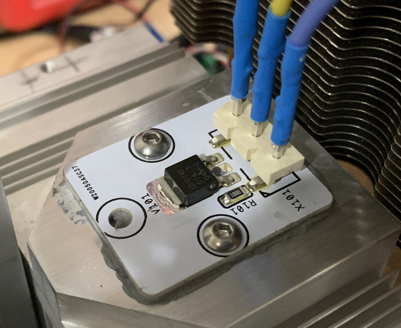
Here it is installed in the amp. Note that I am using crimp wire connectors borrowed from Molex Minifit Jr connector shells. These are good for 9A. I added shrink tube over them but this allows quick and easy swapping of the wires. 2 minute process including adding thermal paste. Imagine having to unsolder this thing from a PCB mounted to a heatsink with hard soldered flying leads for power and speakers. Pain pain pain.
Here it is installed in the amp. Note that I am using crimp wire connectors borrowed from Molex Minifit Jr connector shells. These are good for 9A. I added shrink tube over them but this allows quick and easy swapping of the wires. 2 minute process including adding thermal paste. Imagine having to unsolder this thing from a PCB mounted to a heatsink with hard soldered flying leads for power and speakers. Pain pain pain.
Attachments

Xrk971, are your adapter boads good fit for the LuDEF of ZM? What is the R101 resistor on it and could you please give a link to the pins used in X101 (Mouser or other).
I am not sure, but my guess is that I don’t think it will fit LuDEF as that PCB was designed for the original tiny TO-252 package pins and for clamp with a washer and bolt to the heatsink. This adapter came along after that amp was developed.
The LuFo on the other hand was designed with this adapter board in mind and has a header socket for easy replacement even.
The resistor is a 100ohm 1206 SMT chip - ideally you can use mini MELF here but I was trying to use what I have on hand. The value depends on the amp you are using this for. I spec’d 100ohm for the LuFo. Could be 220R or 47R even probably still work. But best to check amp for oscillation with Oscope. 100ohms does not oscillate as you can see from the clean Oscope trace screenshots plus stable bias current.
The pins are Samtec part hpm-03-02-t-s-vs
You need to order them directly from Samtec. They are not in stock at any major distributor. Samtec is a joy to deal with though. Very fast and professional.
Last edited:
I just received a small shipment of LD1014D’s from an AliExpress dealer (“ShenzenYidastore”). The SMT versions are so much easier to install. Literally 2 min for the whole process vs 10min when you have to futz with bending the legs to lie flat. It tests as an N JFET with 1.7V Vgs on my transistor tester. The easiest thing for me to do to check is install it in my LuFo amp and see if it can play music and make 39w without blowing up.
These devices appear to be thinner (the black epoxy package) than the ones Woofertester sent me. I don’t know if that means anything other than maybe they were shaved and relabeled. They did not come in a tape like the picture shows.
So now you can build an LU-X1000. Bring out the fork lift and upgrade your electric power service.
To easily trace the DPAK LD1014D I made a setup with some hightech tools,
a clothespin 🙂
LDs ordered at "your" seller... I'll have to steal your idea for the clamp, sorry 😉
LDs ordered at "your" seller... I'll have to steal your idea for the clamp, sorry 😉
And I just requested a patent for commercialization 😉
Two updates I did to the setup for easier positioning of the LDs:
soldered a 1mm thick wire on the top island as guidance barrier and glued the bottom of the PCB to the clothespin.
Maybe you could go over what testing could be done with the boards in your video?...assuming simple equipment.
I’ll leave the testing technical details up to the pros - Woofertester can explain. It’s not simple though I’m afraid.
Simplest would be to take a $15 transistor tester and measure the Vgs and match that at least. I am not sure the matching is critical since each is on a separate channel and bias current and Vds are set by a trim pot. The gain is set by the preamp. So unless you plan on running parallel LU1014D’s, maybe not needed? I’ll let Woofertester chime in though.
For the triple IRFP240 (or similar) I suggest matching them at least by Vf so that there is less chance of imbalance or “current hogging”. I matched mine as close as possible with the said transistor tester and measured 0.9A on two and 1.2A on the third. Close enough.
Last edited:
Maybe you could go over what testing could be done with the boards in your video?...assuming simple equipment.
The ZV9 manual has this section. Swap values of the source resistor to obtain 1.5A of idle current. Supply voltage somewhere in the range 3.0v to 3.5v. Ideally it will be the voltage in your amplifier circuit.
I do this measurement at room temp and quickly. You can let it cook and come to operating temperature and then take the measurement.
Attachments

Thanks for the explanation, WT. So for my application in a LuFo, I could set it up to get 3A using a 0.47ohm load and about 4.2v?
But what am I trying to match exactly? Or is matching even needed if each active is in a different amp and the bias current can be adjusted with a trimpot controlling the cascode above it?
But what am I trying to match exactly? Or is matching even needed if each active is in a different amp and the bias current can be adjusted with a trimpot controlling the cascode above it?
Last edited:
- Home
- Group Buys
- Lovoltech LU1014 Power Jfet Group Buy