Hey guys!
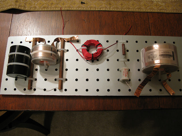
I've finally gotten my component values nailed down and working on the final layout. Here's a pic:
Here's a high-res version:
http://picasaweb.google.com/eisenbarth.ma/Crossovers
Tweeter input starts on bottom left, through cap to the inductor on the far left to ground (2nd order) then a resistor dividing network. Output is taken between two resistors on bottom.
Woofer coil starts on bottom right, then a RCL to ground.
Pretty simple.
Any comments? Can I get away with moving things closer together?
Thanks!!
If you make sure that the inductors are NOT oriented in the same axis ( ie x,y,z ) you minimize magnetic induction and can then move them much closer.Can I get away with moving things closer together?
I've always kept them 6" apart and ensure that if you look through the hole of one inductor you cannot see another inductor. Always has served me well 🙂
Man, this topic reminds me of a young girl showing of her behind and asking if the skirt is too short.
Nice tidy job. Fancy coils and resistors. Whats in front of it?😉
Nice tidy job. Fancy coils and resistors. Whats in front of it?😉
I don't know if you have read AudioXpress 5/01 ( Inductor Coupling ) Dennis Colin:
He outlines a variety of orientation options and coupling results.
Very good article - there was a earlier one that showed the effects of crosstalk on an oscilloscope.
Standard practice is 90 degree orientation and as far apart otherwise
He outlines a variety of orientation options and coupling results.
Very good article - there was a earlier one that showed the effects of crosstalk on an oscilloscope.
Standard practice is 90 degree orientation and as far apart otherwise
HK26147 said:I don't know if you have read AudioXpress 5/01 ( Inductor Coupling ) Dennis Colin:
He outlines a variety of orientation options and coupling results.
Very good article - there was a earlier one that showed the effects of crosstalk on an oscilloscope.
Standard practice is 90 degree orientation and as far apart otherwise
no, but sounds very interesting. I think I can reduce the size a bit.. if I could move the middle inductor down one hole and to the left one position in the grid. Like I said, I usually have things very spread out and haven't tried to really optimize things 🙂
Unfortunately I don't have a good link that covers "mutual inductance"
But I'm sure you have seen illustrations of the magnetic flux lines that expand out from the coil torus - the pole orientation is a line down the center of the hole.
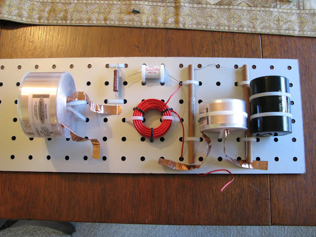
The Big foil air core ( on the far right ) shares the same orientation as foil inductor on the far left.
Turn the Big one 90 degree so it's "hole" axis is oriented right to left.
Then all 3 coil are on different axis and can be closer.
( Not to be boring but mutual inductance is the principle behind transformer action )
But I'm sure you have seen illustrations of the magnetic flux lines that expand out from the coil torus - the pole orientation is a line down the center of the hole.
The Big foil air core ( on the far right ) shares the same orientation as foil inductor on the far left.
Turn the Big one 90 degree so it's "hole" axis is oriented right to left.
Then all 3 coil are on different axis and can be closer.
( Not to be boring but mutual inductance is the principle behind transformer action )
ah. Google helps us here:
http://www.audioholics.com/education/loudspeaker-basics/inductor-coil-crosstalk-basics
http://www.audioholics.com/education/loudspeaker-basics/inductor-coil-crosstalk-basics
Another very good link to this subject
http://www.troelsgravesen.dk/coils.htm
I have actually printed this out and have it above my work bench as an "Aide Memoir"
Regards
Ted
http://www.troelsgravesen.dk/coils.htm
I have actually printed this out and have it above my work bench as an "Aide Memoir"
Regards
Ted
If you don't mind my asking...
Are you a tinkerer/tweaker? ( is this a work in progress & evolving )
OR
You do you want it to be a finished speaker?
Are you a tinkerer/tweaker? ( is this a work in progress & evolving )
OR
You do you want it to be a finished speaker?
HK26147 said:If you don't mind my asking...
Are you a tinkerer/tweaker? ( is this a work in progress & evolving )
OR
You do you want it to be a finished speaker?
nope, tinkering is finished 🙂
My queries were based upon how the crossover was to be integrated into the system.
For example: If I wanted to facilitate experimenting with the crossover further; I would not put the crossover inside the enclosure and instead run terminals out of the cab for each driver. With the circuit external - This facilitates the listening/adjusting cycle.
Many just want it done and mounted securely inside the cab.
I strongly suggest that the crossover circuit and input output points and circuit nodes be identified on the board. ( even if only with a sharpie )
In the same fashion as many printed circuit board have printed on the component side.
This is documentation and will help if/when the circuit is worked upon.
After a while you forget the details of old circuits.
What is the perf-board material ( thickness ) BTW?
- Status
- Not open for further replies.
- Home
- Loudspeakers
- Multi-Way
- Crossover Layout Comments