In the end you got rid of them?
Why?
Because I moved to an apartment and they were too big for that space and too loud for neighbors. The speakers sounded very good though.
Personally, I think MEHs/coaxials offer something not found in traditional multi-way horn speakers so I hope to explore them with horn profiles developed in mabats' software / ABEC and 3D printing. My first prototypes showed promise, but the midrange taps were too small, which compressed the mids when driven hard. The larger the taps are, the more important their shape and placing are. BEM could be very useful in sorting this out, but currently a bit over my skill level in BEM.
Did you ever consider to omit the (presumably) small mids and focus on a big compression driver with bigger mid woofers further down the horn and gluing them together using dsp, according to the synergy principles?
Or develop your own variant in which, by means of an asymmetrical crossover, the midwoofers add some extra weight to the midrange. This probably eliminates the ability to reproduce a square wave.
Or develop your own variant in which, by means of an asymmetrical crossover, the midwoofers add some extra weight to the midrange. This probably eliminates the ability to reproduce a square wave.
Last edited:
Because I moved to an apartment and they were too big for that space and too loud for neighbors. The speakers sounded very good though.
Personally, I think MEHs/coaxials offer something not found in traditional multi-way horn speakers so I hope to explore them with horn profiles developed in mabats' software / ABEC and 3D printing. My first prototypes showed promise, but the midrange taps were too small, which compressed the mids when driven hard. The larger the taps are, the more important their shape and placing are. BEM could be very useful in sorting this out, but currently a bit over my skill level in BEM.
Something that I've found, is that you can put the midrange taps much further out than Danley does. Basically you get maximum output if you do things The Danley Way.
But if you move the midrange taps out further, the speaker begins to operate more like an MTM, where the midrange polar response is determined by center-to-center spacing of the mids, not the horn itself.
Some of the Yorkville Paraline boxes work on a similar principle.
My first prototypes showed promise, but the midrange taps were too small, which compressed the mids when driven hard. The larger the taps are, the more important their shape and placing are.
By omitting the mids, you avoid these issues as well as all kinds of interferences due to taps near the throat.
@Ro808
Yes and no. It would be interesting to try a large CD and slightly larger midbass drivers. I have not found most lagre format drivers outside the very expensive BE drivers that sound hi-fi enough in the top octave, but the HF 1440 looks promising.
I think keeping the driver spacing tight is key for obtaining the result I’m after. Traditional MTMs produce some of the biggest and deepest lobes of all designs. Larger woofers means larger holes in the horn. I think a large CD that allows a low crossover and then using mids in the 4-6” range could be a good compromise for Hifi. We don’t need 130db output.
Another obvious solution is a coax woofer driver with a waveguide like Genelec and to some degree KEF and also Tom Danley do. But I do not know where to get coax drivers of that quality without buying their speakers first.
What piece of the puzzle are we missing to simmulate the effect of the midrange taps?
I made an attempt a couple of years ago, but was not experienced enough to know how to set up the boundary conditions around the taps correctly;ABEC experts - help!
Last edited:
P. Bateman could undoubtedly be of service.
We should be careful not to derail this thread by MEH-related discussions 😉
We should be careful not to derail this thread by MEH-related discussions 😉
I think keeping the driver spacing tight is key for obtaining the result I’m after. Traditional MTMs produce some of the biggest and deepest lobes of all designs. Larger woofers means larger holes in the horn. I think a large CD that allows a low crossover and then using mids in the 4-6” range could be a good compromise for Hifi. We don’t need 130db output.
In a D'Appolito style of MTM, you have thirty degrees of vertical beamwidth. Even worse, the output to the ceiling and the floor is as loud as to the listener!
If you tighten up the spacing from one wavelength to 1/2WL, the beamwidth on axis increases from 30 degrees to over sixty degrees, and the side lobes disappear entirely!
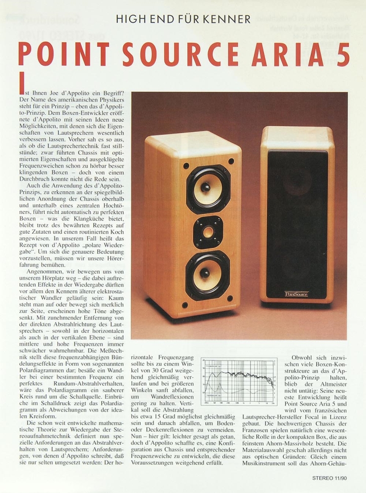
That's why early MTMs looked like this, with very wide spacing...
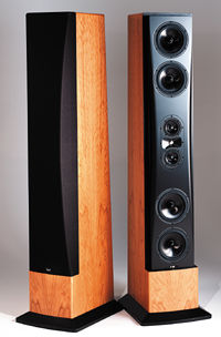
And MTMs that arrived 5-10 years later looked like this.
Basically they figured out that there was a lot to gain from tightening up that spacing.
The Danley speakers use a center to center spacing of about one third wavelength. This is for a number of reasons. Basically the coverage angle, the size of the midrange, the distance from the throat, etc... They all play a part in determining where the midrange taps go.
But a big factor in the Danley speakers is that they're going for maximum output. As you should, if you're selling to the prosound market. If a competing product plays 3dB louder, that can be enough to kill the sale.
But in a home market, we can use some spacing that's not as efficient, but may yield smoother response.
Attachments
Last edited:
What piece of the puzzle are we missing to simmulate the effect of the midrange taps?
I made an attempt a couple of years ago, but was not experienced enough to know how to set up the boundary conditions around the taps correctly
Your simulations look reasonable and match the ones I have done myself or seen. Modelling the driver in the chamber as a flat disc can make the radiation from it more accurate but the radiation going into it less accurate. The driver being a rigid boundary isn't realistic either and that is why the effects are exaggerated from what would occur if the same thing was measured.
Your simulation with no driver behind shows that the holes aren't the real problem but the reflection and resonance from the chamber behind.
I simulated a 50x50 conical horn with and without secondary flare normalized to 20 degrees in an infinite baffle. The diffraction and reflection from the taps will be much harder to see in this than they would in an Ath derived waveguide.
The following is a short study of what a simple conical extension (more appropriate designation than a "slot" in this axisymmetric case) does. It's pretty clear from the pictures what happens.
This is the common part of the definition:
Throat.Diameter = 25.4 ; [mm]
Throat.Profile = 1
Throat.Angle = 8 ; [deg]
Coverage.Angle = 45 ; [deg]
Length = 160 ; [mm]
Term.s = 0.7
Term.n = 4.0
Term.q = 0.996
What changes is the slot length:
Slot.Length = ... ; [mm]
There's really nothing useful in such extension alone, IMO.
Attachments
What if you increase the angle of the extension?
Then it would broaden the peak and bring it down in requency, I think.
The more narrow the extension, the more resonance.
Besides, I find it a little unintuitive that the contour is expanding in the CD and then narrows in the "slot".
I think the "slot" should start with the exit angle of the CD and gently expand.
This is just my guess. (after playing around with throat extension)
Last edited:
I really like the visual aesthetics of biradial horns and how well they sit on / hang below woofer boxes. kind of like the old Altec multicells.
And so I've been trying to make a 2:1 aspect ratio horn for implementing in a 2 way system.
I printed a horn like that that behaves like a CD in the horizontal and like an exponential in the vertical direction.
Going to take some measurements later today 🙂
Is Arta THE software to make polar plots with?
Found an "easy" way to print horns with rollback. Print them in 2 pieces and weld them together with a soldering iron at 200 degrees 🙂
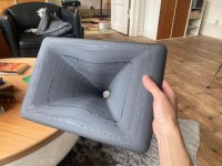
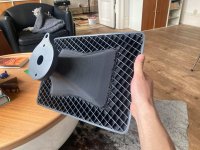


Wow!.. 🙂
- I have never found a way to make shapes like this to actually work nicely. I'm curious about your results.
- I have never found a way to make shapes like this to actually work nicely. I'm curious about your results.
Last edited:
I split the rollback part in Fusion and fill the back of it solid.
After that I print it with no bottom. I believe the rectilinear infill won't **** the effect of the rollback.
After that I print it with no bottom. I believe the rectilinear infill won't **** the effect of the rollback.
This is for throat/extension angles 0 - 15 deg (one sided), 30 mm slot length. All driven by a corresponding spherical wave at the throat.What if you increase the angle of the extension?
Then it would broaden the peak and bring it down in requency, I think.
Attachments
Last edited:
I meant the resulting acoustic behaviour. I haven't succeeded in that, the less in an actual making of those.I split the rollback part in Fusion and fill the back of it solid.
After that I print it with no bottom. I believe the rectilinear infill won't **** the effect of the rollback.
Yeah, I also think the infill won't do any harm, maybe on the contrary.
Last edited:
Your simulations look reasonable and match the ones I have done myself or seen. Modelling the driver in the chamber as a flat disc can make the radiation from it more accurate but the radiation going into it less accurate. The driver being a rigid boundary isn't realistic either and that is why the effects are exaggerated from what would occur if the same thing was measured.
Your simulation with no driver behind shows that the holes aren't the real problem but the reflection and resonance from the chamber behind.
I simulated a 50x50 conical horn with and without secondary flare normalized to 20 degrees in an infinite baffle. The diffraction and reflection from the taps will be much harder to see in this than they would in an Ath derived waveguide.
Thanks for your repply.
To me it seems that the overtall contour and mouth termination is a much bigger effect than some small holes in the WG, as long as those holes are small compared to the wavelength at the crossover. This corrolates well with measurements I have done and seen from others who have drilled holes in their waveguides.
If that is the case, most synergy designs could be improved by using the excellent software and principles Mabat have given us in this thread. A 3D printed horn gives alot of freedom in designing these features compared to woodworking. Hence the motivation to be able to test their shape, placement and interaction with different horn shapes (round, eliptic, square etc). This is not currently well understood from what I can tell.
The motivation of MEH for me, is to have quite large horns working well in small roms, which I think is a bit problematic when the horn diameter gets large. The best of a large horn system and a small fullrange/coax one could say.
Last edited:
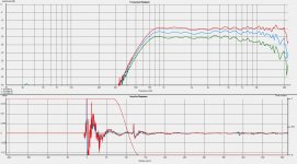
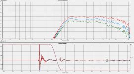
That's not bad 🙂
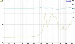
So this is BMS 4550? The impedance looks weird but I suppose this is just how these drivers are. Did you measure the vertical?
So this is BMS 4550? The impedance looks weird but I suppose this is just how these drivers are. Did you measure the vertical?
- Home
- Loudspeakers
- Multi-Way
- Acoustic Horn Design – The Easy Way (Ath4)


