Well,... I could not generate the contour that I really wanted so I used the next best thing. This is my explanation for diffraction.
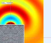
I first pic is my diffraction generator, a simple box 400mmx400mmx500mm with razor sharp edges at 90deg. It uses an R30 ideal driver under constant acceleration. It's shown with a semi-transparent SPL field (dB).
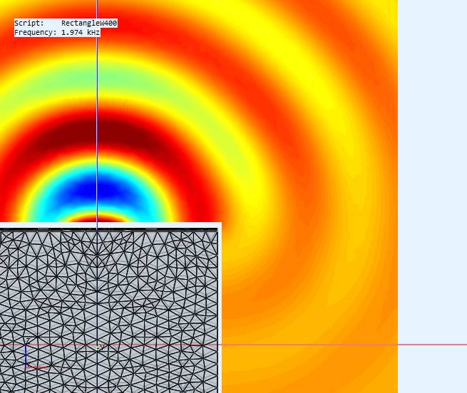
I'm using f=[562Hz, 1K3, 1K9 and 4KHz] as test points. The axial freq response is in pic#2 to show the dips and peaks. There is an amplitude contour and a phase contour for each of the test frequencies as seen top down. We see max amplitude when the phase is +/-90deg and min amplitute at 0/+/-180. We are interested in whether there is a longitudinal wave min or max pressure at the corner.
When the pressure on the corner-face (driver side) is higher than the corner-side there will be a pressure drop at the corner. When the corner-face pressure is high, and the wave pressure changes fast enough, there is a corner-side pressure drop creating a negative wavefront direction as the void is equalized, and it creates a dip.
When the pressure on the corner-face is lower than the corner-side, the corner-face pressure is reinforced by higher pressure from the side. There is a relative rise (less drop) and its in the ideal wavefront direction (positive) and a peak is created.
Pressure changes around the corner will also "pull/push" across the baffle's parallel wavefronts. The wider the baffle the more waves are on it and the harder it is to change them and to equalize around the corner. This make the effect (peak/dip) more pronounced as all the effect is local to the corner.
If the pressure changes slowly (low freq) there will be enough time to slowly equalize around the corner and no diffraction occurs. As the frequency increases, the duration of the pressure differences decreases, meaning less time to equalize, so the effect also decreases.
I first pic is my diffraction generator, a simple box 400mmx400mmx500mm with razor sharp edges at 90deg. It uses an R30 ideal driver under constant acceleration. It's shown with a semi-transparent SPL field (dB).
I'm using f=[562Hz, 1K3, 1K9 and 4KHz] as test points. The axial freq response is in pic#2 to show the dips and peaks. There is an amplitude contour and a phase contour for each of the test frequencies as seen top down. We see max amplitude when the phase is +/-90deg and min amplitute at 0/+/-180. We are interested in whether there is a longitudinal wave min or max pressure at the corner.
When the pressure on the corner-face (driver side) is higher than the corner-side there will be a pressure drop at the corner. When the corner-face pressure is high, and the wave pressure changes fast enough, there is a corner-side pressure drop creating a negative wavefront direction as the void is equalized, and it creates a dip.
When the pressure on the corner-face is lower than the corner-side, the corner-face pressure is reinforced by higher pressure from the side. There is a relative rise (less drop) and its in the ideal wavefront direction (positive) and a peak is created.
Pressure changes around the corner will also "pull/push" across the baffle's parallel wavefronts. The wider the baffle the more waves are on it and the harder it is to change them and to equalize around the corner. This make the effect (peak/dip) more pronounced as all the effect is local to the corner.
If the pressure changes slowly (low freq) there will be enough time to slowly equalize around the corner and no diffraction occurs. As the frequency increases, the duration of the pressure differences decreases, meaning less time to equalize, so the effect also decreases.
Attachments
-
 BoxSPL.jpg48.6 KB · Views: 204
 -
 RectangleCornerPhase@4KHz.jpg84.1 KB · Views: 79
 -
 RectangleCorner@4KHz.jpg52.6 KB · Views: 254
 -
 RectangleCornerPhase@1K9Hz.jpg70.3 KB · Views: 74
 -
 RectangleCorner@1K9Hz.jpg53.8 KB · Views: 245
 -
 RectangleCornerPhase@1K3Hz.jpg66.2 KB · Views: 77
 -
 RectangleCorner@1K3Hz.jpg52.3 KB · Views: 150
 -
 RectangleCornerPhase@562Hz.jpg62.5 KB · Views: 178
 -
 RectangleCorner@562Hz.jpg49.4 KB · Views: 187
 -
 Rectanlge-SPL@3m.jpg33.4 KB · Views: 183
The idea that the impedance change at the edge causes a new "phantom" source to be located there is evidently well accepted, but the details of what exactly happens is just not so easy to describe mathematically.
That's basically what Altec told me in the late '60s, so pretty much 'cast in stone' for me and my [lack of] math skills, though the simple math pipe end correction works well enough for me.
GM
So what is happening at high frequencies that makes them radiate in half space on a box?It's easy for me to envision what is going on in the very HF
Thank you Don!
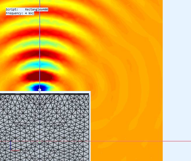
This pic tells best to me what happens at the edge. Pressure variation travelling along the surface suddenly gets more space to expand, and loses pressure (2pi=> 4pi, no baffle step anymore). Now we don't see difraction because wavelength is long enoug, but at 4kHz we see also diffractions from edge "secondary source" (below)
This pic tells best to me what happens at the edge. Pressure variation travelling along the surface suddenly gets more space to expand, and loses pressure (2pi=> 4pi, no baffle step anymore). Now we don't see difraction because wavelength is long enoug, but at 4kHz we see also diffractions from edge "secondary source" (below)
Last edited:
So what is happening at high frequencies that makes them radiate in half space on a box?
Reflection?
Thank you Don!
This pic tells best to me what happens at the edge. Pressure variation travelling along the surface suddenly gets more space to expand, and loses pressure (2pi=> 4pi, no baffle step anymore). Now we don't see difraction because wavelength is long enoug, but at 4kHz we see also diffractions from edge "secondary source" (below)
You're welcome.
Yes, you can still see some HF diffraction but the driver is also getting more directional so you see the main axial beam rings with sharp definition. The "blurring" of the off axis peak-peak rings is because the driver is getting more directional and pressure is not spreading laterally. Notice how the pressure rings on the face get blurred around the corner where the diffraction is happening even for lower frequencies.
Last edited:
This is for the IB mounted driver and it shows no baffle step. I wanted to show the driver directivity changing on an IB. I needed to place the driver slightly off (5mm) the IB, because the IB velocity=0. The ideal flat driver is mounted in a small spherical cap that causes some diffraction at higher freq. Notice the pressure rings are better defined (more uniform across 180deg) even though they are starting to attenuate off axis. I used the same driver and conditions as the rectangle.
.
.
Attachments
-
 IB-cap-Ampl@4KHz.jpg24.3 KB · Views: 65
 -
 IB-cap-Ampl@3K1Hz.jpg25.7 KB · Views: 73
 -
 IB-cap-Ampl@2K4Hz.jpg25.8 KB · Views: 72
 -
 IB-cap-Ampl@1K9Hz.jpg24.9 KB · Views: 72
 -
 IB-cap-Ampl@1K3Hz.jpg23.3 KB · Views: 73
 -
 IB-cap-Ampl@562Hz.jpg21.1 KB · Views: 80
 -
 IB-cap-SPL@3m.jpg26.2 KB · Views: 72
 -
 IB-cap-SPL.jpg26.7 KB · Views: 74
Last edited:
Pressure changes around the corner will also "pull/push" across the baffle's parallel wavefronts. The wider the baffle the more waves are on it and the harder it is to change them and to equalize around the corner.
Is this your theory or from elsewhere? It sounds like momentum.
No that's mine. Momentum is reasonable as well.
I reasoned there would be more volume-velocity moving perpendicular to the bigger baffle surface so it would be harder to change that so you get an increased pressure dip/peak on the corner.
I reasoned there would be more volume-velocity moving perpendicular to the bigger baffle surface so it would be harder to change that so you get an increased pressure dip/peak on the corner.
DonVK, it would seem that shown in the 4k example above that a baffle can be too large for higher frequencies. Is that local discontinuity caused by the baffle's reflection?
I'm not sure, I'm still looking at that. I wanted to plot contours of pressure and velocity but so far I'm stymied. I can't see the phase difference between pressure and velocity.
There is a baffle step of 6dB between 4Pi and 2Pi space and I wanted to see how this was effected by the baffle and driver size. The baffle is always square (maximize misbehaviour) and always 400mm deep, and the driver is always driven by constant acceleration.
I should correct the driver size I mentioned earlier. It's R60 (not R30).
The slope of the 6dB change is dependent on the baffle size, not the driver, as expected. Curves [yellow,green,blue] have 400mm face with different drivers, curves [red, purple,green] have varying face width with the same R60 driver.
Attachments

The sims were done in ABEC / AKABAK. I have no visibility inside the tool, however the docs say it uses the Helmholtz (Kirchoff-Helmholtz) integral to solve for pressure. It's the basis for BEM from what I've read. It's suppose to be able to model radiation, reflection and diffraction effects.
A bit more info and references provided by member fluid here https://www.diyaudio.com/forums/multi-way/338806-acoustic-horn-design-easy-ath4-416.html#post6422524 (post #4157)
Whichever model is used it appears the wavefront wants to expand at an angle relative to it's frequency, pretty intuitive really?
Whichever model is used it appears the wavefront wants to expand at an angle relative to it's frequency, pretty intuitive really?
That's straight out of the ABEC docs, @fluid uses the same program.
I found the baffle step graphs interesting. The wider baffle buys a steeper slope but at the expense of more ripples. Since the step is practically unavoidable, less ripple is a benefit for the narrow baffle.
I found the baffle step graphs interesting. The wider baffle buys a steeper slope but at the expense of more ripples. Since the step is practically unavoidable, less ripple is a benefit for the narrow baffle.
Last edited:
Yes, it's what mabat is using also in that thread, it seems to be the one to use and it's accuracy is confirmed by measurements.


- Home
- Loudspeakers
- Multi-Way
- The frequency dependence of infinite baffle-ism