Pass DIY Addict
Joined 2000
Paid Member
Some time ago, I decided to build Tony Gee's Calpamos speaker, so I ordered a set of crossovers and started gathering the remaining parts. Since there doesn't seem to be much documented about these speakers here on DIY Audio, I thought I'd share my build.
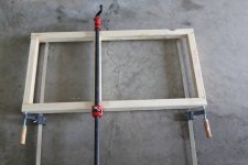
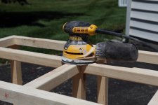
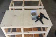
Just within the last few weeks, I started cutting wood to make the boxes. The first challenge that I ran into is that 2x2 wood stock recently became a bit of a challenge to find. My local building supply store still had some stock of 2x4s at pre-pandemic pricing, so I grabbed a few and split them down the center.
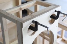
It was a bit of a trick to make sure that everything remained square as I glued up each square and put them together to make a 3D box. More than one of my straight and true 2x4 boards decided to warp and twist a bit after being split down the middle. It took a bit of extra time checking and dry-fitting everything with my T-square before adding glue.
I also bought some caster wheels and made a 2' by 4' dolly so I could move these around the garage a bit more easily. After I built the frames, I realized that I didn't stop frequently enough to make images of my progress.
Just within the last few weeks, I started cutting wood to make the boxes. The first challenge that I ran into is that 2x2 wood stock recently became a bit of a challenge to find. My local building supply store still had some stock of 2x4s at pre-pandemic pricing, so I grabbed a few and split them down the center.
It was a bit of a trick to make sure that everything remained square as I glued up each square and put them together to make a 3D box. More than one of my straight and true 2x4 boards decided to warp and twist a bit after being split down the middle. It took a bit of extra time checking and dry-fitting everything with my T-square before adding glue.
I also bought some caster wheels and made a 2' by 4' dolly so I could move these around the garage a bit more easily. After I built the frames, I realized that I didn't stop frequently enough to make images of my progress.
Attachments
Pass DIY Addict
Joined 2000
Paid Member
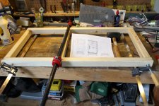
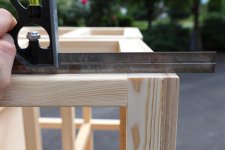
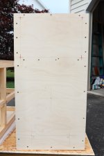
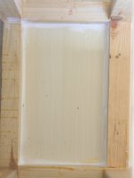
Even though I tried to be as careful as I could, that darn wood glue acts like a lube until it starts to grab and set. Thus, a few joints moved around just a little bit. A few passes with the palm sander and some 80 grit paper made all of the joints flush and flat again.
In these images, the front baffle has already been glued on and flush trimmed with my router for a precise fit.
In these images, the front baffle has already been glued on and flush trimmed with my router for a precise fit.
Attachments
Pass DIY Addict
Joined 2000
Paid Member
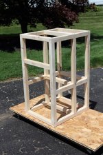
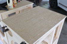
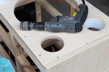
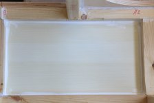
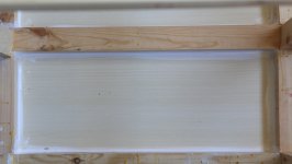
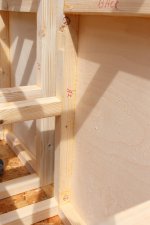
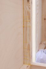
Both cabinets now have 5 panels attached, I left one side panel off of each speaker to make it easier to do some more work inside the cabinet. All panels were glued with copious amounts of glue and "calmped" with lots of 2" deck screws to hold the outside panel to the 2x2 frame. Since the cut out for the tweeter horn reveals some of the 2x2 frame, I made sure to glue the "outer" side of the 2x2 frame where the horn goes so the panel would pop out easily after cutting.
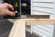
I used a spiral up-twist bit with my router to cut the square hole for the horn, and the driver and port holes. To cut the square holes for the horn, I clamped my T-square across the baffle and used it as a router guide so I'd get nice straight lines.
Planning for the veneer finish turned out to be a bit trickier than I was expecting. Since these cabinets are nearly 24" deep, a single 4' by 8' sheet of veneer won't be enough to cover the cabinets completely. It will be enough for the sides and tops of both cabinets, but there won't be any left over to also cover the front edges of the plywood. Since I still have some thin strips of Bubinga hardwood left over from my Frugal Horn XL build a few years ago, I decided that I'll use those to cover the end grain of the plywood on the front of the cabinet. By using up these scraps, one full sheet of veneer will now be enough to cover the rest of the cabinets.
Since the top, bottom, and side panels extend beyond the front baffle by 15mm, I cut a piece of 10mm thick wood and clamped it to the front baffle. This, added to the 5mm strips of Bubinga hardwood will provide the necessary 15mm overhang. So I clamped the 10mm thick strip to the front baffle to use as a guide while gluing up the top and bottom panels. The side panel was then aligned using the top and bottom panels. All of the screw holes were pre-drilled with a counter sink bit before the screws were driven in.
Attachments
Pass DIY Addict
Joined 2000
Paid Member
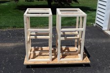
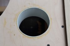
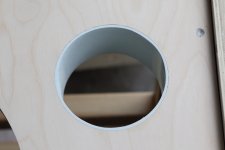
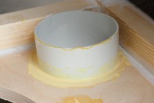
The holes for the PVC vents were just a pinch too small to accept the PVC vents, so I used a 50 grit sanding drum with my drill to enlarge them until the vents fit nice and snugly. Before inserting the vents, I scuffed the outside edges with some heavy grit paper and spread glue on both the inside of the hole and outside of the PVC tube. I then used a rubber mallet to tap them into place and get them almost flush with the front baffle. I smeared a bit of glue around the joint on both the front and back of the baffle, let it all dry, then sanded them flush with the front baffle.
Attachments
Pass DIY Addict
Joined 2000
Paid Member
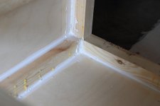
Though I'm pretty confident that I used enough glue and screws (I am about to use up a box of 350 screws that I bought) to make air-tight seals with the outside panels, I took the extra step of caulking all of the internal seams with silicon caulk. Nothing wrong with being doubly sure...
Attachments
Last edited:
Pass DIY Addict
Joined 2000
Paid Member
Cabinet plans are attached below. The crossovers are contained in the writeup on Tony's web page (also attached below), though parts values are not indicated. Those are Tony's intellectual property.
Attachments
Pass DIY Addict
Joined 2000
Paid Member
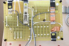
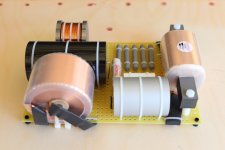
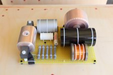
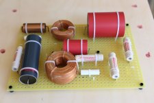
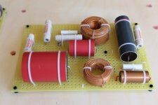
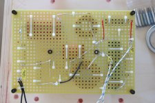
The crossovers are something to behold! I knew they were large, but I was floored when I removed them from the shipping box! They measure 165mm x 240mm and all four boards weigh over 30 lbs. I just attached the wires for the speaker terminals and the drivers as I get ready to mount them in the cabinet.
The woofer crossovers are wired with 12ga silver plated copper wire with a teflon jacket. The tweeter crossovers are wired with 14ga of the same.
The woofer crossovers are wired with 12ga silver plated copper wire with a teflon jacket. The tweeter crossovers are wired with 14ga of the same.
Attachments
Last edited:
I have been looking at this speaker build as well. Then I kind of realised that there was no way to hide this build from the better half. Then I double thought, 75kg per speaker, not a chance in hell that I could move'em up to my attic man-cave once built. I will enjoy your progress! What kind of amp is going to drive these monsters?
./e
./e
Pass DIY Addict
Joined 2000
Paid Member

The crossovers are something to behold!
I am not quite sure if you received the xovers as a kit or as a finished build. They do look nice indeed! However, I'd suggest to rearrange the inductors so they are perpendicular to each other in order to minimize crosstalk between them.
Pass DIY Addict
Joined 2000
Paid Member
- Home
- Loudspeakers
- Multi-Way
- My Calpamos Build