First, let me introduce my DAC, some have already seen it, but for those who haven't, it's a classic old-school DAC with DIR9001 as a digital receiver, PMD100 digital filter and 6 PCM1702s, three in parallel for each channel. The output current of 3 PCM1702s is 7.2mAp-p max. The power supply is given the greatest care, the PCB itself with DIR9001 has three ADP7118 regulators and they are the only IC reg. in the DAC. Other regulators, two +5V for PMD100, +/-5V for PCM1702 and the new +/-10V for AD811 are low noise shunt regulators, slightly improved, made according to Mr.Walt Jung's article and with the help of Mr. Walt. These regulators proved to be much better than the best IC reg ADM7150. There are three transformers to completely separate the power supplies of the digital and analog sections. The rectifiers use CRCRC filters to reduce the ripple as much as possible before the regulators themselves.
And now a little about AD811. AD811 is a high performance video and current feedback operational amplifier with 2500 V/μs. I used it for the first time about 15 years ago with a TDA1541 and two PCM1702, later I switched to tubes, but I wanted to give the AD811 a chance again because I think it deserves it.
The scheme is from Walt Jung from 2/92, published in Audio Amateur, and that's how I connected the AD811 for the first time with op.amp nad filter after AD811. The difference is that now after AD811 there is nothing, the signal goes straight to the amplifier without any additional op amp and capacitor on the signal path. Between AD811 and Le Monstre amp is only the P&G 10K sliding pot.
For this reason, a higher output signal of 3.34Vrms (9.52Vp-p) was chosen, and since the AD811 can provide 100mA at its output, there are no problems with driving the any amplifier at all.
The scheme of the I/V stage itself is simple, the only difference between the classic I/V is in the resistor R1 in front of the inverting input. The output voltage is simply calculated by the formula Vout=-Idac*R2.
The only audio filter(first pole) is R1/C1 and depending on the selected capacitor it ranges from ~40kHz for 2.7nF to ~49kHz for 2.2nF and it is calculated according to the formula fc=1/(2*pi*R1*C1) .
The size of the PCB is 42x80mm. All resistors are RN60 with 100uF/50V UKZ+ 10nF COG SMD for decoupling. The AD811 is an HF beast and should be treated as such. Small capacitors(C1,C5) can be polystyrene, mica or polypropylene.
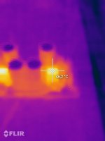
The supply voltage of +/-10V was deliberately chosen that way because of the heating of the AD811 itself, if a small heatsink is placed on them, supply voltage can be higher.
The story continues")
And now a little about AD811. AD811 is a high performance video and current feedback operational amplifier with 2500 V/μs. I used it for the first time about 15 years ago with a TDA1541 and two PCM1702, later I switched to tubes, but I wanted to give the AD811 a chance again because I think it deserves it.
The scheme is from Walt Jung from 2/92, published in Audio Amateur, and that's how I connected the AD811 for the first time with op.amp nad filter after AD811. The difference is that now after AD811 there is nothing, the signal goes straight to the amplifier without any additional op amp and capacitor on the signal path. Between AD811 and Le Monstre amp is only the P&G 10K sliding pot.
For this reason, a higher output signal of 3.34Vrms (9.52Vp-p) was chosen, and since the AD811 can provide 100mA at its output, there are no problems with driving the any amplifier at all.
The scheme of the I/V stage itself is simple, the only difference between the classic I/V is in the resistor R1 in front of the inverting input. The output voltage is simply calculated by the formula Vout=-Idac*R2.
The only audio filter(first pole) is R1/C1 and depending on the selected capacitor it ranges from ~40kHz for 2.7nF to ~49kHz for 2.2nF and it is calculated according to the formula fc=1/(2*pi*R1*C1) .
The size of the PCB is 42x80mm. All resistors are RN60 with 100uF/50V UKZ+ 10nF COG SMD for decoupling. The AD811 is an HF beast and should be treated as such. Small capacitors(C1,C5) can be polystyrene, mica or polypropylene.
The supply voltage of +/-10V was deliberately chosen that way because of the heating of the AD811 itself, if a small heatsink is placed on them, supply voltage can be higher.
The story continues