Approaching noiselessness with the LT3045

Member
Joined 2016
Hello Friends;

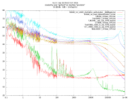
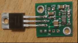
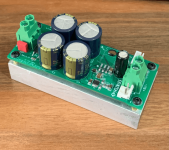
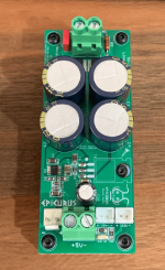
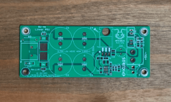
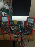
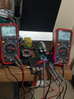
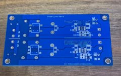
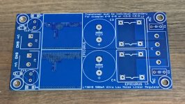
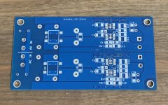
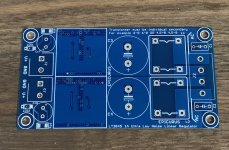
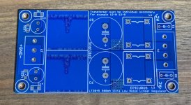
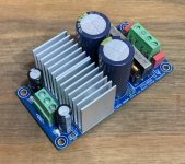
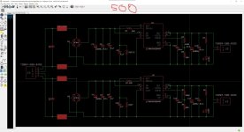
My LT3045 Projects are ready for use. They tested. (I will share FFT measurments) Pcb photos could show you more details.

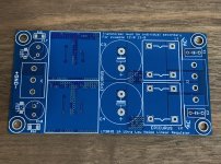
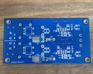
Compact size:63.5x42.7mm

JST, AMP connect and Screw Terminal block can use on PCB

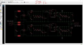
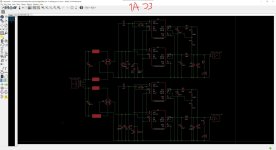
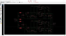
500ma 0.8uV noise and 1A 0.56uV noise sperate dual dac PSU 3.3V 5V 7V 9V 12V ideal for dac and digital audio

500ma 0.8uVnoise and 1A 0.56uV noise symetrical PSU +0- 2x9V 2x12V 2x15V ideal for phono amp preamp buffer and dac output stage

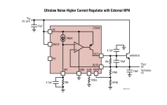
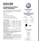
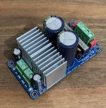
4A 5V LT3045 and transistor desing are for Pi4

Fast starup upgraded

They will send by me who wants them.
 

Attachments

  • indir (6).png
    indir (6).png
    132.2 KB · Views: 535
  • indir (7).png
    indir (7).png
    90.3 KB · Views: 468
  • indir (8).png
    indir (8).png
    108.5 KB · Views: 465
  • indir (9).png
    indir (9).png
    126.4 KB · Views: 422
  • indir (11).png
    indir (11).png
    125.4 KB · Views: 399
  • IMG_3292.jpg
    IMG_3292.jpg
    340.4 KB · Views: 273
  • IMG_3291.jpg
    IMG_3291.jpg
    355.5 KB · Views: 282
  • IMG_3289.jpg
    IMG_3289.jpg
    434.6 KB · Views: 273
  • IMG_3288.jpg
    IMG_3288.jpg
    466.7 KB · Views: 265
  • IMG_3287.jpg
    IMG_3287.jpg
    602.6 KB · Views: 252
  • IMG_3283.jpg
    IMG_3283.jpg
    517.5 KB · Views: 253
  • IMG_3284.jpg
    IMG_3284.jpg
    446.4 KB · Views: 253
  • IMG_3281.jpg
    IMG_3281.jpg
    329.1 KB · Views: 254
  • IMG_3282.jpg
    IMG_3282.jpg
    502.2 KB · Views: 238
  • IMG_3280.jpg
    IMG_3280.jpg
    498 KB · Views: 388
  • 500ma-33.jpg
    500ma-33.jpg
    191.3 KB · Views: 393
  • 500ma-12.jpg
    500ma-12.jpg
    185.7 KB · Views: 384
  • 1a33.jpg
    1a33.jpg
    171.7 KB · Views: 344
  • 1a12.jpg
    1a12.jpg
    182.9 KB · Views: 422
Last edited:
  • Like
Reactions: 2 users
Can you share the noise level measurement setup, and did you do any spectrum measurements ?

Did you compare performance with alternate diode bridges, such as those with a rated recovery characteristic, and with/without series ac input inductance (which may exacerbate any influence from secondary winding leakage inductance)? Did you not want to locate a local smt bypass capacitor directly at the diode bridge dc terminals?
 
  • Thank You
Reactions: 1 user
Member
Joined 2023
Great job. I was about to design a PCB and have JLPCB build it. Could you please share your schematics or Gerber?
 
  • Like
Reactions: 1 user
Member
Joined 2005
Fast start-up is quite essential with LT3042/45/94. It does not impact performance but without it these regulators may cause issues e.g. with DACs. Only adds 2 resistors.
 
  • Like
Reactions: 1 user
Member
Joined 2016
@bohrok2610 You are absolutely right. so I used pgfb resistors in lt3045 4a version. My 4A 5V lt3045 version is now popular with pi4 volumio users. In my tests, the Load Transient Response values of the LT3045 were very good, so the output was 5.116 5.110v even when playing a dsd512 song on a 2tb hdd and an 8.8" screen connected. I did a lot of practice with LT3045.(pgfb resistors etc) These tests are done on es9018s and es9028pro.(dsd256 dsd512 24bit192khz) Regulators work without any problems on dacs.
 
Member
Joined 2005
The problem without fast start-up is just that some dacs require that all power supplies are up when the chip is reseted. Without fast start-up the voltage may come up too slow in relation to reset.
 
  • Like
Reactions: 1 user
Member
Joined 2013
This looks a lot like DIYINHK :D

why even use an LT3045 instead of an implementation like the SuperRegulator by Jung/Didden?

These regulators are most effective when placed closest to the load, on the same board as the DAC/ADC.
Do you intend to use cascade?

I generally like a primary regulation like the Super Regulator (or any other personal preference) and in the DAC/ADC the LT3045/2..
Overkill?
 
  • Like
Reactions: 1 user
Can you share the noise level measurement setup, and did you do any spectrum measurements ?
The circuit is just like that from the data sheet, page 17 or so. The noise performance with the power transistor is within 1 dB, compared to the barefoot LT3042. I'm not even sure if the circuit is the culprit if any. Probably one could get rid of the noise peak if the output cap is slightly damped with a series R. A bigger Cout gives a somewhat lower 1/f frequeny of the noise, but a bigger noise peak. The values from the data sheet are a good starting point for experiments. Cset can be increased without detriment. OK, some people will use hilarious values and will note that there are "effects" from the previous experimentation history. The power on switching via power good is your friend. Above Cset = 100uF tantalum there is not much of an improvement. Probably depends on output voltage. Wet slug tantalums AVX 4700uF/25 seem to be an optimum. At 100$ a pop they won't be everybody's darling. Vishay want twice as much.
At frequencies below 50 HZ, my preamplifier might be partly to blame. (20 * ADA 4898 in par when the pic was taken.)

Just for sure, some people will show up and say "Oh, ah, ceramic capacitors., I'm only lucky with OSCONs hand soldered by a fairie at full moon". I can show them plots of leaky OSCONs that move the 1/f frequency in the KHz range. Oh, not 1/f, more like 1/(f*4). The FFT analyzer has a problem with this, regarding dynamic range. The LT309x Vset IS a high impedance thing.

Input voltage for the measurements were 10 NiMH batteries (14V). They do not add noise of their own. The culprit is the regulator, not Vin, or maybe the pre-amp.

There are more plots at
< https://flic.kr/p/CF3C9r >

Cheers, Gerhard
 

Attachments

  • 24070698809_5528303438_o.png
    24070698809_5528303438_o.png
    41.8 KB · Views: 205
  • 52349011053_6d3472c845_o.png
    52349011053_6d3472c845_o.png
    84.3 KB · Views: 209
Last edited:
  • Like
Reactions: 1 users
Member
Joined 2005
These regulators are most effective when placed closest to the load, on the same board as the DAC/ADC.

I generally like a primary regulation like the Super Regulator (or any other personal preference) and in the DAC/ADC the LT3045/2..
IME if these regulators provide the power supplies to DAC/ADC chips they should be placed very close to the load. But if they power the opamps of DAC/ADC boards then regulators on separate boards work quite well.
 
  • Like
Reactions: 1 users
Member
Joined 2004
H all somebody tried to use a PNP or NPN for highest current ? I need to have more 5A with 15VDC output.

Thanks by advance for your help.

Anod
 
Last edited:
  • Like
Reactions: 1 user
Member
Joined 2016
Yes you can do it. But you need to select fast switching and high current Transistor and big headsink. Input voltage must be between 16.5-18v. I remember stm have a fast switching high current TR 2SD1047 or BUV48. Already D44h11 is 10A butif you want to more then 5A you can selected high power transistor. But you have to select transistor most close to D44H11.
 
Member
Joined 2004
Many thanks to you for your reply, ok I see, do you have a sample of schematics ? I don't have any experience with this LDO.
 
Member
Joined 2016
you can use LT3042 1A schematics. I use this schematic.
lt3045 the same pins. just 500ma
 

Attachments

  • resim_2024-03-24_212221999.png
    resim_2024-03-24_212221999.png
    34 KB · Views: 94
  • resim_2024-03-24_212259171.png
    resim_2024-03-24_212259171.png
    142.5 KB · Views: 92
D44VH10 are no longer produced. I was surprised this week that
it already hits TO-220 transistors. Maybe BD239, but that's too
wimpy to drive my crystal oven.

Last summer I was searching TO-3 power transistors to repair my
HP RLC bridge. At Digikey etc virtually nothing, only a few
military / space qualified ones at shocking prices.

Get them while you can.

BTW Lt3042/45 do not have the same pinout. Same functions,
but the LT3045 has 2 more pins IIRC.
 
Member
Joined 2004
Hi all, many thanks to you for your reply, I really appreciate.

So, what's the difference between parallel ICs and using transistor for highest current ?

Best all and thanks again
 
Member
Joined 2002
IME if these regulators provide the power supplies to DAC/ADC chips they should be placed very close to the load. But if they power the opamps of DAC/ADC boards then regulators on separate boards work quite well.
Isn't this just an indication that the local bypass for the ADC is inadequate? All high frequency energy should come right at the chip's pins by the means of enough capacitance. Any impedance between the capacitance and the chip's pins will reduce the effective capacitance, so layout is critical.
 
Member
Joined 2005
Isn't this just an indication that the local bypass for the ADC is inadequate?
No. LT304x/LT3094 need low ESR/ESL output capacitors due to stability. Larger capacitors (>10uF) do not improve performance. With these regulators using a separate board connected with wires to the load is just asking for trouble (and lower performance).
 
  • Like
Reactions: 1 user
Top