New version of XMachina: 1210622 LINK

Inverting can be allowed or forbidden depending on the checkbox state:


- Bug fix: the application could't recognize potential profits from inverting speaker polarity and now it's corrected. Some of the drivers may be connected reversed:
Inverting can be allowed or forbidden depending on the checkbox state:
- Bug fix: The graph for curve digitization can be loaded from a file (so far only pasting from the system clipboard worked).
- Tab orders have been reorganized (left to right then top to bottom).
- Points can be dragged during curve editing. The previous method has been kept, for switching to "drag point" mode use the context menu:
- Some data structures for axial measurements have been prepared. There is not much that can be done with it in the current version (the measurements can only be loaded and displayed, they are not used for design) .
Attachments


Sorry for the version number confusion. The only difference between the two versions is that in 1210622 it's impossible to load axial measurements (exception occurs, it is corrected in the version 1210624). As these measurements are not used in design yet one can say that the versions are virtually identical.
Any thoughts as to when off axis measurements might be brought into the XO calculation?
It's hard to declare any specific date, but rather months than days. Maybe i'll find a little bit more time for those things during holidays.
To all of you posting here thanks for your constant interest, it keeps me going with coding and experimenting with the crossover machine.
Here is one of my favourite changes in XMachina,

Now this slider is *easy* to understand.")
I will pretend that I had something to do with the language change, but I doubt it...
Thanks for all your hard work, I am super eager to see you incorporate off axis considerations into the XO calculations!
David.
Now this slider is *easy* to understand.
I will pretend that I had something to do with the language change, but I doubt it...
Thanks for all your hard work, I am super eager to see you incorporate off axis considerations into the XO calculations!
David.

Very interesting software. Thank you.
I trying a to linearize a monoway loudspeaker (no crossover) and XMachina haved operated
perfectly.
In red colors the original responce and Z of loudspeake and in green colors the result.
The curve are perfectly same with Xsim simulation.
Great!!!
I trying a to linearize a monoway loudspeaker (no crossover) and XMachina haved operated
perfectly.
In red colors the original responce and Z of loudspeake and in green colors the result.
The curve are perfectly same with Xsim simulation.
Great!!!
Attachments


New version of XMachina: 1211008 with Power Response target
New version of XMachina: 1211008 LINK
New feature: Power Response target with off axis measurements.
It's assumed that some results will be transfered to VituixCad for further analysis and tweaking so the same convention of angle and XYZ position values was used.
As the pdf update date remains undefined, here is some information that may help to get started with the feature.
Create nodes for off axis measurements under way nodes.

Load off axis frds

Frds can be multi-selected in the open file dialog.

Enter angle identifier and angle multiplier.


The frds should now be loaded and displayed.

Note: ON-axis target frds should be loaded into FRD(main) nodes as in previous versions. You can use 0 deg measurements for this, but the delay value based on drivers XYZ and expected listening position should be entered.
Fill the "Power response target" settings in the task editor window. These parameters are gathered in a separate group box. The rest of the task editor window remains the same as before.

If the "sys SPL" weight value is 100% (the "resp. wgh." slider is in the leftmost position) then the power response calculations are switched off. To turn on the power resp target, move the slider to the appropriate position between "sys SPL" and "pwrResp".

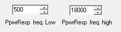
The power response frequency range is defined independently on the system response range. Use the "power resp freqLow" and "power resp freqHigh" parameters.
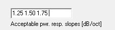
The power response target can be only linear but there may be several target lines. They are defined by the "acceptable slopes" values. XMachina will try to choose the slope that allows to fulfill other targets the most.
Use "mirror H/V" options only if there is symmetry in appropriate plane. The "mirror H/V" option cuts orbit by half and multiplies the result by 2 (this speeds up off axis calculations ~2 times). If there is no symmetry but you want to reuse measurements for negative angles it's better to merge the frds with "-1" as the angle multiplier and use full orbit calculation.

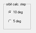
Select angle step value for off-axis response calculation. It is advisable that the step coincides with the value used during the measurements. If not, the measurement data will be interpolated or extrapolated.
The design process remained essentially unchanged. However, it should be taken into account that the calculations are carried out on the basis of several dozen characteristics (not several, as before), so it is worth giving more time to prepare the solution. The analysis of the results remained unchanged, apart from the two additional items on the graph, i.e. the power response curve and its slope.
New version of XMachina: 1211008 LINK
New feature: Power Response target with off axis measurements.
It's assumed that some results will be transfered to VituixCad for further analysis and tweaking so the same convention of angle and XYZ position values was used.
As the pdf update date remains undefined, here is some information that may help to get started with the feature.
Create nodes for off axis measurements under way nodes.
Load off axis frds
Frds can be multi-selected in the open file dialog.
Enter angle identifier and angle multiplier.
The frds should now be loaded and displayed.
Note: ON-axis target frds should be loaded into FRD(main) nodes as in previous versions. You can use 0 deg measurements for this, but the delay value based on drivers XYZ and expected listening position should be entered.
Fill the "Power response target" settings in the task editor window. These parameters are gathered in a separate group box. The rest of the task editor window remains the same as before.
If the "sys SPL" weight value is 100% (the "resp. wgh." slider is in the leftmost position) then the power response calculations are switched off. To turn on the power resp target, move the slider to the appropriate position between "sys SPL" and "pwrResp".
The power response frequency range is defined independently on the system response range. Use the "power resp freqLow" and "power resp freqHigh" parameters.
The power response target can be only linear but there may be several target lines. They are defined by the "acceptable slopes" values. XMachina will try to choose the slope that allows to fulfill other targets the most.
Use "mirror H/V" options only if there is symmetry in appropriate plane. The "mirror H/V" option cuts orbit by half and multiplies the result by 2 (this speeds up off axis calculations ~2 times). If there is no symmetry but you want to reuse measurements for negative angles it's better to merge the frds with "-1" as the angle multiplier and use full orbit calculation.
Select angle step value for off-axis response calculation. It is advisable that the step coincides with the value used during the measurements. If not, the measurement data will be interpolated or extrapolated.
The design process remained essentially unchanged. However, it should be taken into account that the calculations are carried out on the basis of several dozen characteristics (not several, as before), so it is worth giving more time to prepare the solution. The analysis of the results remained unchanged, apart from the two additional items on the graph, i.e. the power response curve and its slope.
Attachments
-
 09_loadoffaxis.jpg26.2 KB · Views: 453
 -
 08_offax.jpg179.7 KB · Views: 453
 -
 06_tsksetings.jpg148.6 KB · Views: 448
 -
 05angle_mul.jpg18.7 KB · Views: 442
 -
 04_angle_identfier.jpg11.2 KB · Views: 440
 -
 03_multiselect.jpg183.3 KB · Views: 444
 -
 02_load.jpg33.2 KB · Views: 94
 -
 01_addnodes.jpg28.5 KB · Views: 444
 -
 07_tglines.jpg140.5 KB · Views: 104
 -
 11_resp_wgh.jpg8.5 KB · Views: 439
New version of XMachina: 1211008 LINK
New feature: Power Response target with off axis measurements.
Very Eager to try this, Thank you!
David.
- Home
- Design & Build
- Software Tools
- Automatic crossover designing with XMachina