Thank you Dave and vanofmonds. Please help me understand. Appreciate Nelson or anyone chiming in on this to help me understand what I am or am not seeing. This is my understanding of how the circuit works and per my reading there is a problem Houston.
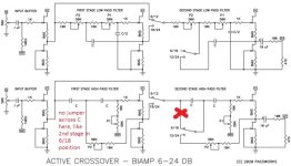
The first and second stage high pass filter sections should be a mirror of each other. There is no jumper in the first stage high pass filter section across the first capacitor. In the second stage high pass filter section when the jumper is in the 6/18 position there is a jumper across the first capacitor. There should not be. It should be identical to the first stage section where the input is going thru the first C then the second C (which equals C/2) and the R of the 10K plus P1 value.
Similarly on the low pass filter section the first stage low pass filter section is a mirror of the second stage low pass filter. There are no jumper positions that would bypass the (10K + P2). This is how it is on the schematic and in the circuit and how it should be per my understanding.
The circuit at it simplest for the high pass filter is the input going into a capacitor and the output being taken between the capacitor with a resistor going to ground. At the frequency when Xc = R is the cutoff frequency. There are four sections and each has to have the same cutoff frequency, if one section is used the slop is -6dB, two -12dB, three -18dB, four -24dB.
For the first stage of the high pass filter there are two C/R networks. The first being the first capacitor (C ) and the R (the 10K resistor and value of P2). The second being the first capacitor ( C) and a second equivalent value capacitor ( C) in series (which is C/2) and the R (the 10K resistor and value of P1). Note that the value of P1 should be twice the value of the P2, see calculator here: http://doublesecretlabs.com/apps/passxo/ The reason is to keep the R/C of each section the same. As R x C = C/2 x 2R; to keep fc the same fc = 1/(2*pi*R*C).
For the low pass section again at its simplest the input going into a resistor and the output being taken between the resistor and a capacitor going to ground. At the frequency when Xc = R is the cutoff frequency. There are four sections and each has to have the same cutoff frequency, if one section is used the slop is -6dB, two -12dB, etc.
For the first stage of the low pass filter there are two R/C networks. The first being the first resistor R (10K + value of P2) and the C value. The second being the value of the first R (10k + value of P2) plus second R (10K + value of P1) and C/2 value. The value has to be C/2 and the equivalent resistor value is doubled to keep each sections R/C values equivalent. As C X R = C/2 X 2R to keep fc the same.
With the jumper across the first capacitor of the second stage, this what I see happening. If you have a high pass filter of say 3.5K Hz and selected C/R values accordingly. In the -6dB position; the cutoff frequency will be 1.75K Hz. If in the -18dB slope position; the first stage section will provide a cutoff of 3.5K Hz at -12dB, which will be summed with the second section of 1.75K Hz at -6dB. If using the -24dB jumper settings, all is good as you will have 3.5KHz at -24dB.
Again, appreciate pointing out what I am not seeing. Not trying to be "that" guy; however, I believe there is an issue and to correct the issue you need to cut the trace between 6/18 and the input of C. Verified that the circuit reflects the schematic, so it not just an issue with the schematic.
Attachments
Last edited:
")

