I'm working on this Dynaco ST-120. All capacitors have been replaced. Sound is okay, but one channel is 10WPC short. Upon investigating, I discovered some voltages are off in the input stage. However I can't figure out why and I've ruled everything out.
All resistors measure in spec. I replaced a few too while investigating too.
I tried swapping out Q1 and Q2 for new replacements.
I checked my solder work. No loose connections or bridged joints.
They are powered by the same supply voltages.
Collector of Q2 has about 5 extra volts on it.
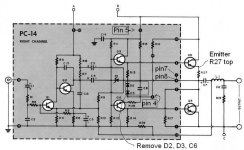
Here's some voltages.
Bad side [Good Side]
Q2: (ECB) 3.3 42 3.9 [3.9 37 4.5]
Q1: 1.41. 3.9 2 [1.29 4.4 2]
R3, 1k: 12V [14V]
R7 1.5k, 17.8 [21]
Voltages on the output side all seem the same. Within 500 or so mV. Negative side of C3 and C4 are the same in both channels.
This should be easy but I've seemingly ruled every possibility out and don't know what else could be going on. Could the circuit just need an adjustment?
Ignore the notes on the schematic, they are for a bias circuit addition I haven't had to do.
All resistors measure in spec. I replaced a few too while investigating too.
I tried swapping out Q1 and Q2 for new replacements.
I checked my solder work. No loose connections or bridged joints.
They are powered by the same supply voltages.
Collector of Q2 has about 5 extra volts on it.
Here's some voltages.
Bad side [Good Side]
Q2: (ECB) 3.3 42 3.9 [3.9 37 4.5]
Q1: 1.41. 3.9 2 [1.29 4.4 2]
R3, 1k: 12V [14V]
R7 1.5k, 17.8 [21]
Voltages on the output side all seem the same. Within 500 or so mV. Negative side of C3 and C4 are the same in both channels.
This should be easy but I've seemingly ruled every possibility out and don't know what else could be going on. Could the circuit just need an adjustment?
Ignore the notes on the schematic, they are for a bias circuit addition I haven't had to do.