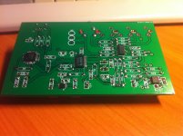
As has been discussed in a few threads, I have been putting together a hobbyist-friendly USB DAC.
Based on PCM2707, PCM1794 and OPA4134, some references have been used from PupDAC, PupDAC Overview .
Other highlights are:
Single-sided PCB suitable for toner transfer.
All passives hole-mount.
Opamp runs on +-5V, allowing for better headroom and larger selection of opamps.
Quad outputs, since I have had enough of splitter cables (desktop system, subwoofer, livingroom cabinets).
Project page so far here: JEDAC - yet another take on a DIY high-end USB Audio DAC
PCB design and construction pics will be up "at some point".
The DAC has now been entirely assembled and is feeding my system. Sounds OK. Difficult to hear a difference from the simple PCM2705 internal DAC though.
Last edited:
I don't wish to sound negative, but you really cannot do a "High End" design on a single sided PCB, only a budget design.
How does the difference between single-sided and double-sided sound?
The main concern of a lot of audioholics is jitter, with at least a double sided design (and preferably more) you can have a proper return plane and control the impedance of the traces better for the digital signals and so get better signal integrity and thus less jitter etc.
A single sided design is a budget design, for high end I would expect all out on all aspects of the design, including the layout. IMO")
A single sided design is a budget design, for high end I would expect all out on all aspects of the design, including the layout. IMO
The main concern of a lot of audioholics is jitter, with at least a double sided design (and preferably more) you can have a proper return plane and control the impedance of the traces better for the digital signals and so get better signal integrity and thus less jitter etc.
A single sided design is a budget design, for high end I would expect all out on all aspects of the design, including the layout. IMO
Yes, that is a rational approach I agree with. It's just that I have come across far too many audioholics who throw reason out of the window and favour some esoteric design that violates most sane design principles. Thus there must be people out there that are "layer purists" who feel multi-layer boards don't sound "right"...
Do you plan on releasing a printed PCB?
Nope, have to DIY...
Why? Maybe do your own PCBs for testing and development but have you seen how cheap getting PCBs made is these days?Nope, have to DIY...
Seeedstudio = Cheap, from China.
OSHPark = Quality, from USA.
Both great services, I've used both and never had a problem.
Hey,
a friend built this project and recommended it to me. First of all, THANK YOU for sharing the build plan. Here's my report...
I printed the circuit with toner transfer. Upon etching I noticed that the transfer wasnt too good, and the ground plane had a lot of holes, almost like swiss cheese. Looking back, I should have dumped the PCB and make a new one. Oh well.
SMD chips were soldered by scratching the copper with a glassfiber pen, cleaning with acetone, treating with flux, and pre-tinning the pads. A lot of preparation, but soldering the SMD chips is a breeze. I just touch each lead with a fine-tip soldering iron. If some more tin is needed, I applied it to the iron, because adding tin directly is askingn for trouble. Soldering went smooth and flawless.
Soldering the through-hole components was business as usual. I did notice that the capacitors in your build plan are bogus. The electrolytic caps do not contain its polarisation. Since there is a negative voltage regulator, it is not as simple as connecting the negative lead of every elco to the ground plane. C5 on your plan is marked as 1uF polyester, but photos show an elco. C2 and C7 show as polyester capacitors on the plan, but photos show a ceramic one. I also think that elco C1 has its polarities reversed.
The USB connectors from dealextreme seem okay. The RCA connectors, however, are so poor and make me cringe. I don't understand why one would use extremely lousy connectors, with such a good DAC. They are hard to fit and fragile, prior to hotglue I ripped off two connectors when connecting the cables. I think I killed 4 connectors, in the process.
Upon completion, my board worked from the first try. I had random crackling and popping sounds, which went away once I rinsed the PCB with acetone and a toothbrush. This ate away a bit of the lettering of the SMD chips. The sound is great, but I don't have the finer knowledge to comment on the fine nuances of the chips or design. I'm using the DAC with a Muse M50 amplifier (while my homebuilt amp is under construction), and a set of homebuilt Mivoc SB25JM speakers (see https://www.flickr.com/photos/thijsd/sets/72157643019041614/ ).
I've tried the DAC on Win7 and Debian, it was plug and play without any trouble. All in all, a great project thats well documented.
Some photos:
An externally hosted image should be here but it was not working when we last tested it.
An externally hosted image should be here but it was not working when we last tested it.
An externally hosted image should be here but it was not working when we last tested it.
I found a nice metal enclosure for the DAC, the price is good, the dimensions are right and it's painted black. It is transverse too, for mounting the connectors.
You can find it on aliexpress as " Aluminum extrusion enclsoure/Controller enclosure /power supply enclosoure 41x147x100mm"
see:
1piece Aluminum extrusion enclsoure/Controller enclosure /power supply enclosoure 41x147x100mm-in Electronic & Instrument Enclosures from Electrical Equipment & Supplies on Aliexpress.com
Hello,
Thanks for awesome project and sharing schematics and files for pcb.
Last year I ordered 5 pcbs from iteadstudios. I had to do some small changes to files. There was couple places where space between conductors was too small. I had never used kicad before, but learned what I needed to do.

First I build one for my Millett Hybrid Starving Student. Soldering SMDs was bit hard because my soldering equipment is bit clumsy. Everything else went well. While doing second DAC I figured that easiest way to solder those SMDs was just solder every pin together and remove tin between pins with desoldering braid.


First one only have one rca connector as you can see. Second one have all 4, those were bit hard to place because of small holes on factory mady pcb. Both PCBs are still waiting to get enclosure.
Setups:
1. PC -> DAC -> Starving Student -> Headphones
2. Raspberry pi(pi musicbox) -> DAC -> Headphones
In both setups DAC worked plug and play. Only minus that I have found with my 2nd setup and with laptop is missing hardware volume control. Otherwise awesome dac. Thanks.
Thanks for awesome project and sharing schematics and files for pcb.
Last year I ordered 5 pcbs from iteadstudios. I had to do some small changes to files. There was couple places where space between conductors was too small. I had never used kicad before, but learned what I needed to do.
First I build one for my Millett Hybrid Starving Student. Soldering SMDs was bit hard because my soldering equipment is bit clumsy. Everything else went well. While doing second DAC I figured that easiest way to solder those SMDs was just solder every pin together and remove tin between pins with desoldering braid.
First one only have one rca connector as you can see. Second one have all 4, those were bit hard to place because of small holes on factory mady pcb. Both PCBs are still waiting to get enclosure.
Setups:
1. PC -> DAC -> Starving Student -> Headphones
2. Raspberry pi(pi musicbox) -> DAC -> Headphones
In both setups DAC worked plug and play. Only minus that I have found with my 2nd setup and with laptop is missing hardware volume control. Otherwise awesome dac. Thanks.
Attachments


Hello, I have build this DAC, and I have a problem. The sound volume is very low. I send 50Hz signal ant measure output vs ground and it is only ~8mV AC. If I measure pcm1794 output pin Iout+ vs ground tester shows only 3mV DC. I fink output from pcm1794 should be higher, or not?


6) put back vertical resistors since they are jumpers
7) removed two outputs
8) further decreased pcb dimensions and number of jumpers
Could you share your kicad files?
I made one for me, I works very well. I have made some little changes too.
I will post pictures after.
thanks!
- Status
- This old topic is closed. If you want to reopen this topic, contact a moderator using the "Report Post" button.
- Home
- Source & Line
- Digital Line Level
- JEDAC - yet another take on a DIY high-end USB Audio DAC