Hello!
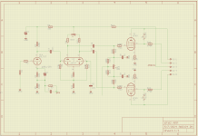
I am trying to calculate component values for my next amplifier project which schematic I have attached below. The power stage is ok for the moment, I know I can run a B+ of 350Vdc for triode connected 6F6G from the valve datasheet. I would like to use 6N7GT as a LTP phase splitter, as it is accessible to get at a decent cost. I know there is a russian equivalent valve (6N7S) but I have already built some amplifiers based on russian valves and I want this one to be different. The input stage I am thinking that could be one section of 6SL7 triode.
Anyway, the problem I get into, is that I can't find a good loadline for the 6N7GT phase inverter. I am sure that I am missing something as I am not an expert in designing valve schematics. Also, it would be a good thing if somehow would be possible to elevate the cathode of the 6N7GT to around the value of the Ua of the input stage, so I ca have them DC coupled.
Can you please have a look at the schematic and make any suggestions?
Thanks in advance for any bit of info.
Regards,
Mircea
Attachments

KDMAudio,
I like your schematic. But . . .
1. The jumper for Triode mode is not enough to switch from Ultra Linear mode to Triode wired mode.
On your schematic . . .
With the jumper in place, the screen is connected to the plate (and with no screen stopper resistor between the screen and the plate).
And, it also connects 470 Ohms from the primary Ultra Linear tap, to the primary Plate tap (essentially shorting out the signal with only 470 Ohms).
A 6000 Ohm plate to plate primary, with 40% Ultra Linear tap, is 1500 Ohms from plate to center tap; and 240 Ohms from Ultra Linear tap to the center tap. Consider what happens when 470 Ohms is connected from 1500 Ohm tap to 240 Ohm tap. 1500 - 240 = 1260 Ohms.
Connecting 470 Ohms across 1260 Ohms primary taps is a very heavy load (not a short, but a real power hog, power that goes to the 470 Ohm resistor, and not to the loudspeaker).
You need a screen stopper, one end connected to the screen, then the free end of the resistor to connect to a single pole dual throw switch (SPDT).
Connect the primary plate tap to one End of the SPDT switch, the other End of the SPDT to the Ultra Linear tap;
then connect the free end of the screen stopper to the switch "rotor".
Caution:
Do not change the setting of the switch from Ultra Linear to Triode mode when the amplifier is running.
Your output tubes, output transformer, loudspeaker drivers, and your ears will not like the results of powered switching (very large transient "signal" noise; might cause destruction of one or more of those things.
2. The input stage bypass capacitor is shorting out the global negative feedback. Move the bypass cap from the bottom series resistor, to across the top series resistor (the resistor that connects directly to the input stage cathode.
3. You have RC coupling from the input stage to the phase inverter, and RC coupling from the phase inverter to the output stage, and the primary inductance of the output transformer primary.
That makes the circuit have 3 low frequency poles. Like a Williamson amplifier.
The poles must not be at the same frequency, or you end up with an oscillator, not an amplifier.
One solution (as you already mentioned) is to Direct Couple from the input stage plate, to the phase inverter grid. Then there is only one RC coupling and one primary inductance, for two low frequency poles.
There are many schematic examples that show DC coupling those two stages.
That is 2 poles, intrinsically more stable when global negative feedback is used; versus with 3 low frequency poles.
4. I once had a 1938 Philco with a single ended 6F6 output tube, and a 6-1/2, dynamic speaker driver. Sounded real good for an early AM radio.
Back then, many AM stations transmitted much wider bandwidth than todays AM transmitters. Up to 10kHz lower and upper sidebands.
Have Fun!
Last edited:
Thank you for your feedback! I realized that I did not mention about the way the schematic was drawn.
On the PCB, if I go for triode mode, the screen resistors won't be installed, and the jumper will be installed.
If at some point I want to change for UL, then I will leave the jumper uninstalled and connect only the screen resistors.
That is why the schematic was done like that.
Thank you for the observation with the cap on the input stage.
I have found some NOS valves at an European supplier. To be honest, I am attracted by the shape of the glass lamp.Is 6F6 still a readily available tube type?
")
Connect a 100 Ohm screen stopper right at the screen. Connect the other end (free end) of the 100 Ohm resistor to the jumper (with the jumper
in-place you have triode mode, including the 100 Ohm screen stopper.
With the jumper removed, connect the free end of the 100 Ohm screen stopper to the Ultra Linear tap for Ultra Linear operation.
No switch required; but using the above connections, a 100 Ohm screen stopper is always present.
Just one way to do it.
Glass envelope shape you like is called a Shoulder Tube.
No offense but it's a bit of a odd design attempting to do everything but nothing really optimal. In my experience multi-configurable amplifiers are no meat no fish. You can still use the same board to change the output stage but in a fixed way, not switchable.
With the triode output stage I would use an input transformer as phase splitter (an affordable and good Hammond Studio series, for example) and would not waste 90V or so in the cathode. That would allow to raise the anode current of the 6N7 easily by 35-40%, using the same anode resistors, get more a bit more anode voltage with more headroom and/or overload.
Anyway you can try with R9, R13 =100K, R17=680R, R11=330R, R12=30K. That should result in about 90V anode voltage and 1.5mA for each triode of the 6N7 but just 1V bias. That's a bit on the low side and maybe one can still tweak it a bit for better linearity but not a whole lot of different tough.
The most famous 6F6 PP amp I know is the Western Electric 133A that uses input transformer to split phase and completely push-pull through out. 349A tube is their version of 6F6G. It does sound good and I prefer it over the more ubiquitous WE 124. It offers the princely sum of 4 watts that can drive big horn speakers comfortably.

Hello!
Thank you for your suggestions. I think I managed to find a good bias point for the input stage and phase inverter. I have attached below the new schematic.
Can someone please have a look ?
Also, if someone has good experience with LT spice and wants to help with a simulation, that will help a lot!
Thank you in advance!
Mircea
Attachments

You have a jumper for Triode Wired.
But the schematic always has the screen stopper connected to the Ultra Linear tap (at the same time).
You need another jumper from the screen stopper to the Ultra Linear tap.
That way, you put in Only one jumper, Either the Ultra Linear jumper, OR the Triode Wired Jumper.
Easy PCB fix.
R10, potentiometer . . . It can adjust Either the plate voltage balance, Or the signal amplitude balance.
Those do not always happen at the same potentiometer setting.
That is why a real high impedance CCS is used, instead of the 18k cathode resistor. With the CCS, and matched plate loads, the signal balance is Intrinsically very good.
If the plate voltages are far apart, then as long as there is enough voltage across the plate to cathode, and enough voltage across the plate load . . .
then there will be enogh + and - plate voltage swing to drive the output tube grids fully.
Last edited:
I would call it "just about experience" for me. As with any simulations, the usual caveats apply.Also, if someone has good experience with LT spice and wants to help with a simulation, that will help a lot!
Thank you in advance!
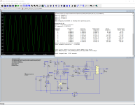
Anyway, here we go
I reduced B+ to get them closer to the datasheet limit values. 350V is well above the maximum values, especially for G2.
Output transformer used for simulation is 8K:8. The datasheet includes a pentode mode PP class A example, using 10K:8 OPT.
LTP modified to use a CCS in the cathode as recommended by @6A3sUMMER.
My own experience of LTP phase splitters was 'unhappy', and shown in both transient simulation ringing and AC simulation differences between one side and the other.
The tail CCS is a good idea, but still I found that the cathode drive of the 2nd half gave a slightly inferior (delayed) signal to the lower (pull?) tube, and this upset the HF performance and feedback.
So I would consider also simulating a concertina phase shifter as that's much better synchronised between the push and the pull (only impedance differs, IIRC). The problem then is to drive big triode with it, as the concertina likes a very light load, which means more tubes, or running the 6F6 in pentode mode, which sort of defeats your quest of using it in triode mode
So perhaps that's not an option here..
I can see you are using 1kHz too, in your simulation, I'd suggest switching up to 20kHz as certain limitations are easier to spot there 🔭 You may have to faff with the .tran statement to get meaningful THD figures though, due to the inevitable phase shift being a bit more noticeable there. 📏
I hope that helps, there are many more knowledgeable people on here than I, so your mileage may vary !
Thank you gentlemen for your input on this! It is good to see that this design is advancing.
@jcalvarez Your simulation helps a lot! Now what would be interesting to check ( please excuse me if I am asking too much) the frequency BW at -1dB let's say. I understand that this is an ideal scenario but at least we can check what next mods to do on the schematic.
Another question is what would you recommend as feedback ? Schade or NFB ?
Best regards,
Mircea
Here is the simulation at 20kI can see you are using 1kHz too, in your simulation, I'd suggest switching up to 20kHz as certain limitations are easier to spot there 🔭 You may have to faff with the .tran statement to get meaningful THD figures though, due to the inevitable phase shift being a bit more noticeable there. 📏
<deleted>
About LTPs, never had issues with them. Having said that, I don't claim to have done a lot of time measurements, but definitely never had issues with balancing them.
PS Ignore this, it is a version with concertina, sorry. Here is the correct one, at 20K
Attachments
Last edited:
Here you go (10 to 30k sweep)Now what would be interesting to check ( please excuse me if I am asking too much) the frequency BW at -1dB let's say. I understand that this is an ideal scenario but at least we can check what next mods to do on the schematic.
I tried Schade once on a single ended prototype, it actually performed worse, but it was my fault, I had a relatively low plate resistance stage and applying Schade to it made not much sense. I have never tried it for push-pulls, but there are plenty of examples around. For this topology I use global negative feedback. It requires a decent output transformer, but it is pretty stable, at least in my amplifier.Another question is what would you recommend as feedback ? Schade or NFB ?
- Home
- Amplifiers
- Tubes / Valves
- 6F6G PP Amplifier design