Is supporting a corrugated membrane on the long side really a good idea? I mean, that bend that is needed to move the membrane is really opposite of what the corrugation is trying to mitigate, no?
I think so. The corrugations will stiffen the the membrane from side to side which is what I want.
This of course requires that the gasket must be really soft and squishy since it needs to account for the movement. I assume I will print it in 55A shore hardness with thin walls and pretty low % of infill. Something like this:
And I plan to use 1.5 mm carbon steel, and only if it proves to be too weak go to 2mm.
And the threaded inserts will of couse be a weak part but I don't think they need to be that strong . They just have to be strong enough such that I can mount the driver first rear then front instead of having to add both the front and rear steel sheets + magnets at the same time. When the front is mounted and screwed with screws and nuts then I will be able to unscrew the middle screw into the insert since it will not be as strong as the outer 2 screws + nuts.
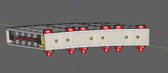
But you are correct that I might need to think more of how I can mount the front without gambling to destroy the membrane since the magnets will be strong. My dad had a great idea that I could use long non magnetic axle steel rods to help guide the front plates:
- Mount the rear plate into the side with a small weak screw (blue) into the threaded insert.
- Add membrane + gasket
- Use long stainless non magnetic axle steel rods to guide the front plate with magnets down such that it locks in the indexed pegs. Then replace 1 rod with a screw (red) and nut untill all rods are replaced. Then repeat for each front steel plate.
- Remove the now redundant weak blue screws into the threaded insert.
I have ordered from Aliexpress, so remains to be seen if they are actually 50x3x3 mm...Where to get magnets like 50x3x3 mm?
Attachments


Sounds like a great plan, OllBoll.
I'm still worried though that the threaded inserts will not be strong enough when you mount the front plate.
The mounting "red" screws might also be too short, perhaps you should start with longer ones?
I'm currently using two mm carbon steel.
It failed when I tried nine columns of magnets, the plate bulged one mm in the middle, so now I will try five columns as you have.
I will post the result in my current thread.
I'm still worried though that the threaded inserts will not be strong enough when you mount the front plate.
The mounting "red" screws might also be too short, perhaps you should start with longer ones?
The front plates won't be mounted in the threaded inserts. Only the middle blue screw will go into a threaded insert which temporarily mounts the rear plates to the edges.
And yeah, the red screws which will be what actually holds everything together will probably be longer.
And about the thickness yeah. Note that my current models are a lot shorter than yours. My have 40 mm width with holes where yours has 80 mm. And across the magnet gaps I have a lot more steel supports. I have 24% supports where yours has 5%.