Timely post!, I finished assembling my filter yesterday and was ready to powertest it and the connectors did not match. With a little work it became clear that the connector on the power supply was not big enough to take the center pin on the pcb jack. I checked all the part numbers and the datasheets and everything said 5.5 x 2.5, but the connector on the cable from the wallwart was 2.1. Everything matched the post from Nelson earlier in this thread and the info on the ACA mini. It's as thought the specified switcher for this project needs an additional -xxx added to the part number.Pay attention to the pin diameter of the power input jack (post #62, CP-037B-ND). The center pin is 2.5 mm.
I ordered and got, very quickly, the right connector which is attached and the unit is working away fine.
Much tuning and experimentation to come.
Check yours, the cable end connector, not the board jack, when it arrives!
Skip
Of course.If you have more than one source, probably after....
I surely ever dont want to be cracking wise, here…
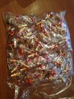
But. I think these ultra cheapo plastic RCA snap in connectors soldered to the fine boards looks like extra small low quality flaccid plastic dildos, duct taped, as a statement, on the motor hood on a classic ultra high quality Mercedes Benz.
Instead of the appropriate three pointed star.
But…
Then again. Thats just me ❤️😎🤚
Yea, thats why i did not state ”cheap”.
I clearly stated ”cheapo”. And yes, they actually look extremely plastic cheapo.
Well. 🙂
On just a little more serious note. 🙂 There is simply absolutely nothing wrong with a extremely solid, durable and stable connection. Thats simply a scientific fact.
Both from a sonic point of view, and from what can really solidly stand the test of time.
😎
Yea, thats why i did not state ”cheap”.
I clearly stated ”cheapo”.
I never knew there was a difference.
Bear in mind that the board was designed for these connectors so why not keep it simple?. You may also end up concluding that the board doesn't work for you so why spend more money than you have to?
"Non cheapo" RCA PCB mount types exists. I got some by a mistake and just use them as standard chassis mount connectors.
I think you could get those to fit the PCB......more or less.....and then at same time have the RCA connector secured to the chassis which is nice. Then no stress will be on the solder joints.
The PCB mount RCA connectors used for SSII headphone amp are something in between. Rather cheap but made with two screw holes to secure connectors to chassis. The easy way is just to use normal chassis mount RCA connectors and use very short wires to the PCB. That would probably be my approach.
Attachments
That's what I intend to do as well.The easy way is just to use normal chassis mount RCA connectors and use very short wires to the PCB. That would probably be my approach.
Very good 
A nice thing with those "expensive" PCB mount RCA connectors I pictured is that you don't have to "fiddle" with the thin ring used for the gnd connection that only have electrical contact with pressure which is usually not very high (because of the plastic isolators (Neutrik types are an exception)). With those PCB mount types you have "direct" connections
A nice thing with those "expensive" PCB mount RCA connectors I pictured is that you don't have to "fiddle" with the thin ring used for the gnd connection that only have electrical contact with pressure which is usually not very high (because of the plastic isolators (Neutrik types are an exception)). With those PCB mount types you have "direct" connections
I probably got them here from Don Audio:
https://www.don-audio.com/RCA-Cinch-High-End-PCB-Panel-Jacks-Gold-Set
https://www.don-audio.com/RCA-Cinch-High-End-PCB-Panel-Jacks-Gold-Set
If you want to pay a lot more there are also these (they are not PCB-mount but still have the "direct connection"):
https://www.hificollective.co.uk/phono_sockets/cmc.html
It requires a lot heat (large heavy tip on solder iron) to solder the Gnd wire.......
The metal used is Cu and then with an exotic kind of plating......of free choice
https://www.hificollective.co.uk/phono_sockets/cmc.html
It requires a lot heat (large heavy tip on solder iron) to solder the Gnd wire.......
The metal used is Cu and then with an exotic kind of plating......of free choice
- Home
- Amplifiers
- Pass Labs
- Full Range EQ


