GAS PSP3500.1d going into protect

Member
Joined 2024
Hello, repairing my brothers PSP3500.1D (or trying to). Issue in the title.

Tools I have: Multimeter (has diode mode, beep, etc), soldering iron

How it happened: He was listening to music at a low volume, shut off the car and went to the shops, when he came back the amp was dead.

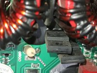
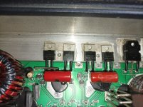
What I've done: Opened it up, found a IRFB7437 with the drain leg melted (see image below). Its 4.7ohm (4R7) gate resistor also was dead. Replaced both, still goes into protect.
IMG_20240420_203345.jpg


Diagnostics:
There is no short between the RCAs and speaker outputs
There is an increasing resistance (goes from ~0 to ~135ohm) between the power and ground terminal.
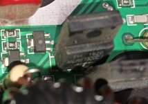
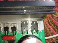
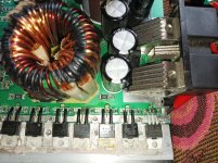
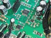
There is an increasing resistance (goes from ~0 to ~135ohm) between the drain and source (2nd and 3rd pin left to right) of all these fets (see image)
Rest of the fets seem fine
IMG_20240426_200320.jpg


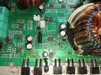
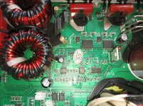
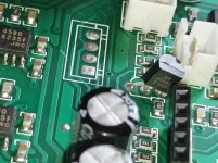
Other side of the amplfier:
IMG_20240426_205827.jpg


I hope we will be able to find the issue, thank you in advance.
 
Last edited:
Member
Joined 2024
And checked with my very DIY osciliscope, the middle pin of the fets circled in the picture posted before gets 12v DC (remote not connected). Ground was connected to the chassis. No change when remote gets connected. Didnt see any DC voltage on the output terminals
 
Member
Joined 2024
Yes, about 5v on the pin 1

Unknown freq on pin 2, as my oscilloscope is an arduino 😂

heres a screenshot from the UI, maybe can calculate it, as the time is known, the voltage is going thru a ~65.5x voltage divider as i didnt know how high of a voltage i would be dealing with on the rails
1714210072099.png
 
Member
Joined 2003
Do you have the diagram for the amp?

The scope display isn't useful or the output is wrong. It should be an 80kHz signal. With the scope set to 5us, you should have only about 4 complete cycles.
 
Member
Joined 2024
I do not, online i couldnt find anything about the amplfier. The oscilloscope isnt good because its not supposed to be an oscilloscope, its an arduino, lol
 
Member
Joined 2003
Can you post a high resolution photo of the MCU and the area around it?

What are the transistors that are being used as a buffer between the 2010 audio driver IC and the output transistors?
 
Member
Joined 2024
Not very high res, so just took more, but closer shots. Basically took shots of the entire board
 

Attachments

  • IMG_20240427_115820.jpg
    IMG_20240427_115820.jpg
    355.9 KB · Views: 21
  • IMG_20240427_135037.jpg
    IMG_20240427_135037.jpg
    311.9 KB · Views: 24
  • IMG_20240427_134536.jpg
    IMG_20240427_134536.jpg
    663.2 KB · Views: 20
  • IMG_20240427_134544.jpg
    IMG_20240427_134544.jpg
    619 KB · Views: 21
  • IMG_20240427_134552.jpg
    IMG_20240427_134552.jpg
    640.3 KB · Views: 18
  • IMG_20240427_134601.jpg
    IMG_20240427_134601.jpg
    595 KB · Views: 21
  • IMG_20240427_134609.jpg
    IMG_20240427_134609.jpg
    586.5 KB · Views: 18
  • IMG_20240427_134729.jpg
    IMG_20240427_134729.jpg
    366.6 KB · Views: 17
  • IMG_20240427_135518.jpg
    IMG_20240427_135518.jpg
    528 KB · Views: 21
Member
Joined 2003
I've been trying to find a diagram that's close and this amp is a lot of parts from the Brazilian amps, unfortunately, a lot of different models.

I'll keep looking. Hopefully someone will see this and is more familiar with the Brazilian amps than I am.

If you try to power up, at the instant that you apply remote voltage, do you see any sort of pulses of DC or square wave on the inputs of the 27324 PS driver IC?

Does it go into protect before you apply remote voltage?
 
Member
Joined 2024
It only powers up and goes into protect when the remote voltage is applied. No remote is no power up like it should be.

I dont see any dc voltage, but i do see pulses of something, possible that its square wave that is too fast for the arduino. The pulses stop after the amp goes into protect. It goes like: remote applied, then the 3 leds (power, clip, protect) turn on after eachother, until the power and protect start flashing.
1714219738205.png
 
Member
Joined 2024
not sure which ones you meant, but from what i tested, i didnt see much. Only now noticed there is an voltage regulator going to the 2 IR2010S, that regulator isnt getting any supply
 
Top