I like to share the basic idea I had to construct the system ( with multiple mems mics):
-use a hula hoop sort of ring to which you attach the mics in x degree steps, have 2 mics at every x degree point, spaced by d to get the inner and outher layer measurements
-rotate with a stepper motor a Rotation 1 point in x degree steps. This wil produce the equatorial measurement points to get an easy spherical harmonics fit
-if you have enough microphones, you will only need this rotation point
-with less microphones, add Rotationpoint 2 as a sort of gearing wheel, if this is rotated by x degree steps, all possible resolution steps can be made, even with only 2 mics.
The advantage of this setup is that is is mechanically strong and balanced so it can be made light and move fast and precise. With 3d printing it should be quite doable to make it in, for instance, 45degree segments that are then assembled to form the loop
just my 2 cents, I was starting to create this a while back, but as said life happened. I now feel that sharing this could lead to things getting done and more people enjoying it
I tried to find out was what was going wrong with the USB ports. I made this measuring box (here in a half built state):
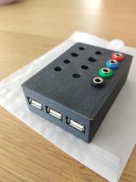
I found nothing weird.
I bought a 3 euro USB hub at a 'dollar store' and it seems to work fine with my laptop.
I wrote some python code (https://github.com/TomKamphuys/NFS) and can interface with the arduino and tic, so the motion part is working. I'm working on the sound part. First I tried pytta, but I found pyfar (https://pyfar-gallery.readthedocs.io/en/latest/index.html) which looks promising. I tried the example and it does things, but somehow I don't understand the outcome. I'm still working on that.
Python definitely is a more allround language: logging framework, unit test framework, proper OOP, modern IDE (pycharm) and a lot of packages for almost anything you want to do.
Back to work
What commands are sent out to grbl? I am wondering if another form of motor control could be made to work relatively easily. Like the Marlin 3D printer controller I have just dissasembled.I wrote some python code (https://github.com/TomKamphuys/NFS) and can interface with the arduino and tic, so the motion part is working.
Simply gcode 
Edit: Well... There is a bit more to it. I added a level of indirection in the code, so you can in theory have something completely different for each axis. Below you see a part for my build: a combination of grbl (arduino + cnc shield) and tic.
Edit: Well... There is a bit more to it. I added a level of indirection in the code, so you can in theory have something completely different for each axis. Below you see a part for my build: a combination of grbl (arduino + cnc shield) and tic.
Python:
    radial_mover = GrblXAxis(grbl)
    angular_mover = TicFactory().create('../config.ini')
    vertical_mover = GrblYAxis(grbl)
    scanner = Scanner(radial_mover, angular_mover, vertical_mover)
Last edited:
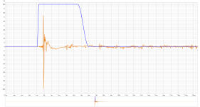
IR measurements are now also possible. Here is the reference signal and the measurement exported as .wav file. IR can also be calculated, but can't show you that at the moment; you'll have to believe me 
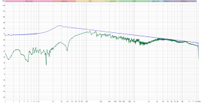
Configuration, logging and testing is coming along nicely.
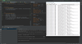
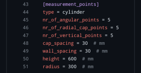
I still have generate the measurement grid, but we're getting close to doing a measurement (set).

Configuration, logging and testing is coming along nicely.

I still have generate the measurement grid, but we're getting close to doing a measurement (set).
I still have to measure my Ath waveguide properly. Would be nice to measure a waveguide with an NFS, both made on this forum.
I could even use my tube amp (https://www.diyaudio.com/community/threads/european-el-cheapo-ish-build.367296/), but that might not be really practical
I could even use my tube amp (https://www.diyaudio.com/community/threads/european-el-cheapo-ish-build.367296/), but that might not be really practical
great!
Still a bit rough around the edges, but in principle everything is in place.
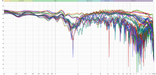
View attachment 1309305
View attachment 1309304
Haha yes, it just decided to do measurements while moving lol
Also there are quite some speed/time optimizations that can be made.
But I think that is quite obvious
Wait for move ready not working properly yet. So I just waited 3 seconds for the movie. That turned out to be too little for the large move. It buffers the motion commands on the arduino. Once it has emptied that buffer, motion and measurement is in sync (or should I say out of sync) again.
'Premature optimization is the root of all evil.' Time optimization is not all. I would also like to minimize position errors by doing everything in the same direction, even though an up/down/up/down/... scan is faster. But we could support both. It's just code that needs to be written.
'Premature optimization is the root of all evil.' Time optimization is not all. I would also like to minimize position errors by doing everything in the same direction, even though an up/down/up/down/... scan is faster. But we could support both. It's just code that needs to be written.
Quite a lot of monkey work in this case.It's just code that needs to be written.
Like nests and nests of if loops and that kind of stuff.
Which makes it very receptable for (silly) errors.
I personally would do a if statement instead of waiting.
Or in other words, let the end of a movement be the trigger.
To do this even better, I would also suggest working with encoders on the steppers. Although we can also just abuse the back EMF from the motors for this.
From a higher level point of view, it might be easier to translate everything to a logic coordinate system.
That's a bit of work up front, but will make everything much easier down the line.
In fact that way you can always sync position and measurement.
That was the case in my octave implementation and my plan in python. It's not functioning properly though.I personally would do a if statement instead of waiting.
Or in other words, let the end of a movement be the trigger.
Encoders have their advantages. I had to increase the counterweight and loosen the gantry wheels as the mic boom sagged a bit because of slack/backlash in the counterweight assembly. Encoders would have noticed that.To do this even better, I would also suggest working with encoders on the steppers.
But for now it's working good enough. It's kinda becoming my default answer to all your improvement ideas 🙂
What do you mean by logic coordinate system?From a higher level point of view, it might be easier to translate everything to a logic coordinate system.
That's a bit of work up front, but will make everything much easier down the line.
In fact that way you can always sync position and measurement.
Last edited:
Not exactly rough. This is pretty good.Still a bit rough around the edges, but in principle everything is in place.
Random height for the measurements? Or will we be able to specify midpoints at say tweeter or in between the tweeter and the woofer. Many times there are actual focal points for the crossovers. And measuring these areas could be important. Getting close is one thing but chasing these points to get for instance that imaginary 20k response that audiophiles believe exists or manufacturers wish to have "evidence" of for marketing purposes.
Instead of working with how many steps you have to take from/to each position, work with a coordinate grid system from a certain reference point.What do you mean by logic coordinate system?
Obviously under the hood it's the same, but it makes it just easier to work with.
In that case also the (file) naming will be super straight forward, since you just have to see at what coordinate you are and what measurement had been done at the same time. (Either like really in time or what time in your loop).
With an encoder you also don't have to care to much about hysteresis (backlash), those things cost close to nothing these days and you just mount them directly on your current steppers.
In that case you actually have real direct data in terms of position, instead of assuming it from the amount of steps.
Which aren't even real measured steps.
One missing step early in the entire measurement cycle and all data can be entirely wrong!!
Problem is that you currently have no control or clue if and when that happened.
Which is the biggest problem.
We could argue how big the chances are, but in practice we all know there is always something that can go wrong.
Murphy will get you, often at moments that are the worst 😄😄
Almost like you are thinking!But one could make it as they want. Just implement the next() function.
So my take away points from your experience is that perhaps a little stronger profile? The counterweights being the determining factor?
How is the creep deformation on the 3D printed parts? That will either be robust enough or start to slowly move around.
I see you have sized this perfectly for a small two way. Larger measurements are needed here.
So are these parameters easily adjusted?
To be able to do a true 1 meter measurement is still a requirement for almost everyone.
And I have loudspeaker designs that are over 2 metres tall! So taller will be needed here. Most likely a bottom rolling support sled will be required. Even with a counterweight the distance required is not exactly small.
- Home
- Design & Build
- Software Tools
- Klippel Near Field Scanner on a Shoestring
