I measured 100mV bias on 33h...
Between points A and B = 100mV ???
I measured 100mV bias on 33h...
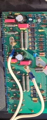
So instead of 4x0.1R in the circuit diagram, you have 2X0.33R ?Look the photo
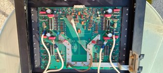
OK, thx. i saw that classic look and didn't recognize it at all ....mlloyd1 this is a Infinity RS1B electronic crossover
Hans the resistors are 4 for side, like 331 and 336 amp.So instead of 4x0.1R in the circuit diagram, you have 2X0.33R ?
Calculating again, this means 100mV/0,33R = 330mA or 33mA/transistor.
I would expect twice that amount.
Hans
One side
Hans the resistors are 4 for side, like 331 and 336 amp.
Not 0,1ohm x 4 but 0,33 x 4 for side
")