I think in my post before that maybe it is better to use single buffer-driver for each digital bus line.
like 74HC1G126
Redirect Notice
.
OR
74LVC1G125
74LVC1G125 Datasheet PDF , NXP : Bus buffer/line driver; 3-state
.
same pinout
like 74HC1G126
Redirect Notice
.
OR
74LVC1G125
74LVC1G125 Datasheet PDF , NXP : Bus buffer/line driver; 3-state
.
same pinout
Last edited:

With the great help of dqfan I draw the attached schematic. I am not sure if I should use an SPDIF receiver like the AK4118 to feed the I2S input or go for an isolated and reclocked USB board such as the JLsound: what is the best sounding and most flexible way?
Attachments
Hi jpk73
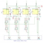
this is selector and recklocking line. For each I2S line. Without decoupling power supply. For Flip-Flop use same family 2xF-F like for the buffer. Resistor could be MELF types?
.
Check with scope all sygnals in the I2S lines. MCK should be rising edge like SCK and LRlatch. I told You this because some digital interfaces have inverted MCK line. Amanero have correct all lines. I found some xmos int. have inverted MCK line. IF it is a case ADD one inverter in the MCK clocking line for ALL F-F, And bare in mind that R signsl integrity will be lower value 33ohm guess because of feed 6 x F-F in recklocker. But measure and trim.
.
(330 ohm is too high value for R signal integrity. It is usually around 91 - 120 ohm depending on F and position on scope measurements with trimmer pot.)
Attachments

No every line should be "recklocked". With 2 F-F in serial You will have delay for one MCK cycle but for ALL lines and all sygnals will be same rising/falling edges like they was before. Also 2 x F-F per line is for metastability issues. And there are no "mixing" diferent F in same IC. standard F-F are dual per IC. With standas MCK-s in USB/I2S interfaces of 22/24 MHz, max SR to pass trough the recklocker is 192Khz. Because SCK becomes same as MCK in higher SR like 352/384KHz, and recklocker need at least 2x higher MCK than SCK...
BUT there will be no isue with PMD200 because even for the 2X OS set. requires lower SR on the input. So This recklocker will be good.
BUT there will be no isue with PMD200 because even for the 2X OS set. requires lower SR on the input. So This recklocker will be good.
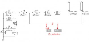
Many thanks, Zoran! I tried to make a schematic using 74LVC logic according to your suggestion, see attached diagram. Should I better take MCLK for the flipflops directly from the input? This circuit will be injected in the Naim PCB at the points marked in red on the attached Naim schematics: attachement 01 shows the clock circuit of the Naim, attachement 02 shows where I intend to inject the other three I2S signals, and attachement 03 shows the PMD200. I will read the LRCK signal with my MCU to detect the sampling rate: the point where I take the signal to the MCU is after the i2s selector and before the reclocking stage: is it correct like that?
Attachments


Last edited:
I will read the LRCK signal with my MCU to detect the sampling rate: the point where I take the signal to the MCU is after the i2s selector and before the reclocking stage: is it correct like that?
Yes
.
Should I better take MCLK for the flipflops directly from the input?
Yes but You will have 2 MCK one from Naim another from USB/I2S interface.
Add one selector for MCK too?
.
Note that MCK should be in phase with other lines. Rising edge when rising SCK and FCK. Please check that with a scope. IF it is not, use inverter. Check for Naim and Interface.
.
Maybe to use oscilator circuit (with some logic after, like You have) then just Crystal? For this 16.x MHz
About PMD MCK
"External Clock Mode (input) – XTIM determines if the master clock is 384xFs (HIGH) or 256xFs (LOW) where Fs is either 44.1 or 48 kHz. Additional master clock rates of 512 or 768 x Fs are available from Program mode." from pdf
.
USB interfaces have ususaly 512 X Fs MCKs. 2 oscilators for each Fs base 44/48,
If it is possibile somehow to instruct PMD to accept 512xFs MCK would be better. Then recklock with same MCK.
.
I can use a transistor to invert the signal, or should I better use logic IC?Note that MCK should be in phase with other lines. Rising edge when rising SCK and FCK. Please check that with a scope. IF it is not, use inverter.
USB interfaces have ususaly 512 X Fs MCKs. 2 oscilators for each Fs base 44/48, If it is possibile somehow to instruct PMD to accept 512xFs MCK would be better. Then recklock with same MCK.
It should be easy to program the PMD for various MCLK rates. But I am still not sure where I should take the i2s signals from:
Maybe to use oscilator circuit (with some logic after, like You have) then just Crystal? For this 16.x MHz
Like this? Taken from here:
Attachments


Last edited:
"I can use a transistor to invert the signal, or should I better use logic IC?"
.
Better with logic inverter. Sometning like in this PDF but just if needed. Mesaure with scope rise/fall MCK with recpect to SCK and Fs. If MCK is "inphase" no need to invert...
.
Better with logic inverter. Sometning like in this PDF but just if needed. Mesaure with scope rise/fall MCK with recpect to SCK and Fs. If MCK is "inphase" no need to invert...
Attachments
It should be easy to program the PMD for various MCLK rates. But I am still not sure where I should take the i2s signals from:
:
I think that You will use I2S selector before PMD100? So that You can use PMD also for the I2S additional input?
.
You have 2 options to place recklocker Before PMD200 and/or after PMD200, prior to DACs?
.
With placing reclk after the PMD You have to cut-out traces with addition of one data reclk line.
.
If You put recklocker after selector than all sources will be recklocked before PMD200. Like You alredy scetch?
.
Remember recklocker need at least (minimum) 2X higher F than highest F in the line - SCK to acheive self function. Could be higher of course 4X, 8X...
.
I spot that You have oe MCK for SAA ic and PMD ic? If it posibile use 22/24 MHz for SAA and same for the PMD?
If You already have 16.9344 MHz master clock for SAA + PMD i think that You can use it to try the reccklocker for 44.1 KHz base.
.
If the word window length 24 bit per I2S data channel (from SAA) than it will be 44100 x 48 = 2.116800 MHz SCK line. That is 16.9344 / 2.1168 = 8 times MCK / SCK ratio.
.
If the word window length 32 bit per I2S data channel than it will be 44100 x 64 = 2.8224 MHz SCK line. That is 16.9344 / 2.8224 = 6 times MCK / SCK ratio.
.
that is the round, even numbers and the recklocker wil work for the 44.1KHz Fs?
.
If the word window length 24 bit per I2S data channel (from SAA) than it will be 44100 x 48 = 2.116800 MHz SCK line. That is 16.9344 / 2.1168 = 8 times MCK / SCK ratio.
.
If the word window length 32 bit per I2S data channel than it will be 44100 x 64 = 2.8224 MHz SCK line. That is 16.9344 / 2.8224 = 6 times MCK / SCK ratio.
.
that is the round, even numbers and the recklocker wil work for the 44.1KHz Fs?
HI, guys.
Sry to chime in so late. But wanted to share a chip I successfully used in a project to switch between two I2S sources. I found it to work very well.
SN74CB3Q3257PWR
Cheers, Kovax
Hi Kovax
")
Yes it is OK, but the diferent F and lines are interfering inside on the DIE of chip. It is better to use single ICs for each line. And power planes are common for each of multiple modules inside of 4X or 8x chip. With single SW power lines are separate and probably smaller ground bouces are?
.
But offcourse single chip x 4 consumes a bit more space on the PCB...
Better with logic inverter
Thanks Zoran! Please have a look at the red marked "?" in this diagram: I still don't understand from your explanations where I should take the signals for reclock and LRCK detection
Do I need to take the two signals before or after the i2s switches? The i2s switch itself is before the PMD200, and the reclocking stage would be between i2s switch and PMD200...From Your sch
https://www.diyaudio.com/forums/att...-naim-cd-player-pmd-200-stand-dac-reclock-jpg
Recklocker working only with one of the switch position, one input. Other inpyt when choosed, override recklocker?
Probably You want to use recklocker just for external I2S source?
Another thing: @pin26 (CL16), SAA You should have output MCK. Please check with scope.
Yes the tap for the Fs check is OK. But that is only for the CD, SAA Fs
- Home
- Source & Line
- Digital Source
- mod NAIM CD-player with PMD-200 into stand alone DAC