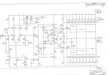
Hi, please excuse the thread revival, but post #2 in this thread is the closest I've seen to being representative of the S300 I'm working on.
(I should note that the one I'm working on has MPS-U10/-U60 pre-drivers, though, which I think might make it a little older than the schematic. The number on the PCB is 550486, if that's useful.)
Owner's complaint was hot running. Both channels respond appropriately to offset adjustment - and seemingly to bias adjustment, too, as long as the offset has been zero'd first. Both channels can produce some output, but one distorts severely.
The distorted channel also exhibits a behavior I've never encountered before: When the output swings + (either dynamically, or just setting the offset to +100-200 mV or so), both halves of the complementary section (last 3 stages) conduct increasingly as the + voltage swing increases. (This is with no output load.)
As the + swing increases, the base-to-base voltage measured at the pre-drivers increases - I'm baffled about why that would be. The current in the CCS that loads the VAS stage does not change, at least not the emitter current. I suspected some weird leakage in the (-)-going pre-driver (labeled 2N5415 in post #2) , but I've tried replacing it with no behavior change.
I'm stumped. There's either some interesting difference in my unit's circuit vs the post #2 schematic (likely enough) or I'm missing something (very likely).
Thanks for any clues!
So, define running hot, the heat sinks should be around 50C on the SA/3. The power supply is simple but you just need to check the voltage rails are good +/- ? after the rail fuses! If so, then feed the input a sine wave and walk though the Front End board with an Oscope and see where the signal goes bad and look for problems in that area of the circuit. I have worked on many of the SA models and the output devices are not used to their limits so are very reliable.Owner's complaint was hot running. Both channels respond appropriately to offset adjustment - and seemingly to bias adjustment, too, as long as the offset has been zero'd first. Both channels can produce some output, but one distorts severely.
Thanks for the suggestions. I don't think new front end boards are economically viable for a customer project, and I think I'm past the point where signal tracing will help to further narrow down what's wrong with the original board.
It feels like there is already a Big Hint in the observation that the base-to-base voltage of the predriver stage increases as the output voltage goes positive, but I can't figure out what could cause that when the current in the VAS stage doesn't appear to change. Any thoughts on that aspect?
It feels like there is already a Big Hint in the observation that the base-to-base voltage of the predriver stage increases as the output voltage goes positive, but I can't figure out what could cause that when the current in the VAS stage doesn't appear to change. Any thoughts on that aspect?
- Home
- Amplifiers
- Pass Labs
- Threshold S300/SA3 service manual, shematics