AoE x-Chapters 2x.14, PG508 output-stage gain
In section 2x.14 and Figure 2x.88 we're primarily concerned with having enough gain to make a good amplifier at 50MHz. The estimated 20pF of node capacitance presents about 800 ohms of reactance at 10MHz, and drops to only 160 ohms at 50MHz. By comparison, the input impedance of the output emitter-follower transistors would be about 10k (for a 50-ohm load and beta = 100).** Below about 800kHz that would become the main limit to loop gain.
I recognize that would be of significance to, for example, e diyAudio enthusiast, thinking about distortion. If gm = 0.2, the loop gain from DC to 800kHz would be about 5k or 74dB.
** At high frequencies transistor beta is also dropping. If their fT was about 300MHz, see Figure 2x.80, beta would be about 30 at 10MHz, leading to their EF input Z dropping to about 3k, which is still much higher than the 800 ohms due to Ccb. I have found that Ccb, see Figure 2x.77, is more often the killer parameter in high-frequency amplifier design, than fT, which is the parameter most people think of as significant. This is especially true if you try to run your amplifier at lower currents.
Finally got time to resurrect this project and finalize my two units I build up.
Getting into the process of testing both (I did functional test a year ago so knew they worked OK).
I already found that both have a substantial DC offset, one unit 0.4V, the other 1.2V. As far as I can see there's no offset nulling foreseen.
So my question is, anyone here has seen this too, and what would be the best way to null it?
Jan
Attachments

Last edited:
Not an unusual symptom for an almost classic inverting CFA + folded cascode. They are not famous for small offsets.
Jan, leaving the TL431 without decoupling (10u or more electrolytic, not a 0.1u ceramic, that would guarantee oscillations!) is a bad idea. C02 must be 680uF not pF.
Jan, leaving the TL431 without decoupling (10u or more electrolytic, not a 0.1u ceramic, that would guarantee oscillations!) is a bad idea. C02 must be 680uF not pF.
Last edited:
Hmmm, those TL431's are indeed not decoupled. Need to check what is actually on the boards, it's been a while.
I was to believe that the R06/C02 do not set the gain but were intended to set for best stability, and that I do remember: I had to adjust them for stability with load.
But I'll check with the designer ;-)
Jan
I was to believe that the R06/C02 do not set the gain but were intended to set for best stability, and that I do remember: I had to adjust them for stability with load.
But I'll check with the designer ;-)
Jan
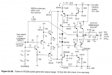
O, looking at the inspirator for this amp, the Tek PG508, you see the same stability circuit. This is not to set the gain; that is set by the ratio of the source impedance and the feedback resistance.
Attached from The Art of Electronics, The X-Chapters, Paul Horowitz and Winfield Hill. Get that book!
Jan
Attached from The Art of Electronics, The X-Chapters, Paul Horowitz and Winfield Hill. Get that book!
Jan
Attachments
Last edited:
You are right, I stand corrected. That’s a phase correction at HF.
Just by inspection, this amp doesn’t seem excel in stability. In particular the lead-lag with a 2pF capacitor is concerning, in general I cringe when I see anything under 10pF, for audio purposes, but also this lead lag within 680pF which raises the loop gain around 10MHz, in order to correct the phase, is not in particular appealing to me.
But I am sure it works fine if properly tuned. I would expect a strong implementation (layout, wiring, power supply decoupling) dependent tuning process.
Yes, you are right. With optimal tuning there is still a 3dB hump at a few MHz, down 3dB at around 10MHz.
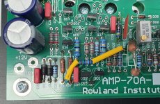
And, with all due respect for whoever laid out the PCB, it's suboptimal to say it nice.
I've been twitching to do my own but never got around to it, there's always other projects that interfere ;-)
Jan
And, with all due respect for whoever laid out the PCB, it's suboptimal to say it nice.
I've been twitching to do my own but never got around to it, there's always other projects that interfere ;-)
Jan
Last edited:
The following mod decreases the output DC offset from 1.2V to less than 50mV.
Connect a resistor of 180k from the +15 supply to the input summing point (junction R01-R02A-R03 etc.).
After about 10 mins of warmup it's almost zero, but it wavers a bit with temperature etc. Anything better would require a small DC servo add-on; I might still do that.
Jan
Connect a resistor of 180k from the +15 supply to the input summing point (junction R01-R02A-R03 etc.).
After about 10 mins of warmup it's almost zero, but it wavers a bit with temperature etc. Anything better would require a small DC servo add-on; I might still do that.
Jan
Attachments


Hmmm, those TL431's are indeed not decoupled. Need to check what is actually on the boards, it's been a while.
...
Jan
But you knew since April 19 that "in the original circuit there is a dominant source
of noise given by the noise of the TL 431 regulators in the folded cascade circuit".
It is the output signal distortionI have no idea what the scope picture shows.
Jan
How do I debug it?
- Home
- Amplifiers
- Solid State
- Winfield's 100W DC-10MHz 1000V/us amplifier