Yet Another Aleph J Build

Member
Joined 2019
Paid Member
Guide offers that specific option too. It even says that if you're not sure, ask in the forum. :) Matter of preference.

They're not delicate, you just don't want stress on the solder joints for the legs or stress on the legs. Nothing to get overly concerned with. Hit the joints with the iron, and all will be right with the world.

Step 55 - bullet 1 -

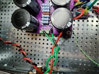
"Some people like to wire their PCBs before mounting (Starting at step 41) and installing the MOSFETs. That allows mounting the boards only once. That is perfectly valid. PO-TAE-TOE, PO-TAH-TOE. If you are unsure, ask for guidance. Since you've read the guide a few times before building, you've already made your choice before you got here."

:)
 
Member
Joined 2023
Regular Greedy Boy doesn't need bloody Guide!!
We all have, or at least the rest of us, need something to strive for! In the meantime its awesome to be able to build the creations of so many incredible minds. Maybe w/ a little luck there will be an Iron Pre Super Special ZM design in my future! ;)
 
Member
Joined 2019
Paid Member
^ From what I can see, you're progressing very nicely! Heck, without guides to help me get started, I'd never be the massive dodo I am today blowing things up without guides. :joker:

:cheers:
 
  • Like
  • Thank You
Reactions: 2 users
Member
Joined 2020
Zen Mods circuit is a real sissyamp. All it needs is a little tender love. Of course under MZM’s guidance :rofl:
image0.jpeg
 
Member
Joined 2020
Yes yes, but as we all know: your pa isn’t my pa! We are moving into third generation realm now :rofl:

He did it, he said it, you interpret it and tell me in vikinghorn language.

So my last mod is a result of your intepretation of your translation of Pa’s original circuit into greenhorn non-fallable language. So maybe we are even talking 4th gen.
 
  • Like
Reactions: 1 user
Member
Joined 2019
Paid Member
Right channel PSU side - (Where) is the negative DC wire from the rectifier connected to the filter board?

I admit I'm not in love with the Red, Green, Green for your wiring. Mixing up your GND with your V- is not my idea of a good time. If you have not already that I cannot see, I would strongly consider labeling the end of each of those green wires with something very obvious to avoid confusing them, particularly if your plan is to twist them.

BE CAREFUL and observe that the L and R sides of the PSU boards do not have the same 'relative' positions for V+, V-, and GND. They ARE NOT mirror images. READ THE LABELS before connecting the amp boards EVERY TIME. Say it out loud to yourself.

:2c:
 
  • Like
Reactions: 1 users
Member
Joined 2014
Your PSU should be grounded to chassis right? If you're relying on the bolt and metal standoff to make that connection you'll want the PSU board bolted to the standoffs.

[Edit]: Some close up shots of the amp boards might help. One thing I maybe see....maybe...is a little strand of copper wire that's free and sticking out. Is there a chance that could contact that lovely gold finish and short out? I'd double check no frays on any wires just to be sure. Cut away, or resolder, if you find some.
Screenshot_20240422_112333_Chrome.jpg
 
Last edited:
  • Thank You
Reactions: 1 user
Member
Joined 2023
With the exception of screws to attach my blank DIN plates she's just about done. Allowing the goop to cure on the front panel LEDs, then button her up to do final bias!
Pre Button Up (FILEminimizer).jpg
 
  • Like
Reactions: 1 users
Top