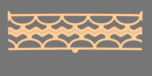
I guess this is better. One thing to look for on this one is that when a half circle is compressed it looks like it will expose and non linear resistance as you approach xmax. Why - because the only way the material close to where the neighbour half circle meets can go, is sideways. But it can go sideways because the neighbour is also bulging (yellow star)... i.e. stiffness increases.,,, This is what an ordinary spider also do but in a different way - the accordion structure is stretched to exhaustion.

Maybe a little distance between the base (at/above the yellow star) of the half circles?
//
Maybe a little distance between the base (at/above the yellow star) of the half circles?
//
Maybe a little distance between the base (at/above the yellow star) of the half circles?
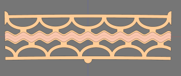
Like this?

I also added a red representation of the peak-to-peak xmax of +- 0.5 mm which is roughly what I aim for. But in practice I'd be content as long as I get +- 0.15 mm with minimal distortion.

The current design has a mechanical xmax between the magnets of +- 1.5 mm.
did you make multiple separated coils you can attenuate ? only possible when going horizontal coils ?
I havent gotten that far yet. But yes, that would be one of benefits of of that design.
Aha. That makes sense.
And I just realized something: It is not enough to just compress each side up to the xmax but ideally the other side should push up to xmax too.
And I just realized something: It is not enough to just compress each side up to the xmax but ideally the other side should push up to xmax too.
- I make each half say 0.5 mm taller and then compress them slightly when mounting. That should make the membrane require less force to move I think since the compressed potential force of one side can be used to trade for compressing the other?
- They are the same size rougly. But then one side is compressed and the other side is pulled, requires more force to move the suspension thus less efficient?
Last edited:
so the traces move horizontal ? and magnetsLike this?
View attachment 1315061
I also added a red representation of the peak-to-peak xmax of +- 0.5 mm which is roughly what I aim for. But in practice I'd be content as long as I get +- 0.15 mm with minimal distortion.
View attachment 1315069
The current design has a mechanical xmax between the magnets of +- 1.5 mm.
I havent gotten that far yet. But yes, that would be one of benefits of of that design.