@alexcp I just want to stress you are a hero. Earlier I gave the other built PSU a good cleaning with 99% iso, let it sit to ensure it was good and dry, swapped it in just now. No changes to my previous post.
I resoldered all the pins for the comparator, no change.
Per your below plan, it works just fine after performing step 1. Do I proceed with 2 through 4?
I resoldered all the pins for the comparator, no change.
Per your below plan, it works just fine after performing step 1. Do I proceed with 2 through 4?
- Disconnect the PGOOD wire coming from the power supply and check if it works without it. I am still concerned that both boards behave identically - errors and faults are common but rarely identical on different boards.
- Pulled pin from PSU side, voila, 2 seconds or so after power on we have a brighter LED and clear relay click.
- If you can, remove Q53. If you don't, just make sure Q53 is closed by shorting R60. An even better idea would be to connect a battery of some other isolated low voltage source between PGOOD (negative) and -V (positive), driving the gate of Q53 below the negative rail with something else than the PGOOD from the power supply.
- Short С43 and С44. This effectively will take the comparator out of the circuit. (In a through hole board, we could just pull it out of its socket, but not here).
- Now we have only R55 and C53 left to prevent the relay from working. Measure the resistance of R55 with your DMM. If it is ok, remove С53.
Last edited:
That's good news. So we have comparator the R55C53 delay, and the Schmitt trigger working normally. Just to make sure Q53 works, try shorting the PGOOD input on the amp's board to ground - it should make the relay turn off. When you disconnect PGOOD from ground, the relay should turn back on after a delay.
Then, let's see what is wrong with PGOOD. Since PGOOD uses a separate rectifier with a small filter capacitor, it has a large ripple:

The amplitude of the ripple depends on the filter capacitor, C14 (here, 10μF), and the forgotten resistor (here, 2.2 kOhm) that discharges C14 when the AC power disappears. If the ripple becomes too large, Q53 will be opening on the positive peaks and discharge C53. You can see on the picture that in my case, 2.2kOhm is just high enough. The easiest way to check the ripple is with an oscilloscope if you have it. If you don't, just try increasing the discharging resistor and see if it works any better.
Then, let's see what is wrong with PGOOD. Since PGOOD uses a separate rectifier with a small filter capacitor, it has a large ripple:
The amplitude of the ripple depends on the filter capacitor, C14 (here, 10μF), and the forgotten resistor (here, 2.2 kOhm) that discharges C14 when the AC power disappears. If the ripple becomes too large, Q53 will be opening on the positive peaks and discharge C53. You can see on the picture that in my case, 2.2kOhm is just high enough. The easiest way to check the ripple is with an oscilloscope if you have it. If you don't, just try increasing the discharging resistor and see if it works any better.
Your suspicion in regards to shorting PGOOD input to ground was correct (this was performed without PGOOD connected to the PSU.)
I do have a scope, but I have been in the midst of a major clean of my work area, it's easier to try a new resistor. Top of the drawer was a 5.6k CMF55. Swapped the 2.2k MBB for it, and we are in business!
I am glad to know that it was something so simple. I checked back in my pictures I took last night, I have a picture showing the LED glowing brighter, and one without, so I know I wasn't imagining things. While I understand the ripple difference here, what would have attributed to a difference last night vs today on my mains?
PGOOD power is now -23.22vdc
Q53 gate -23.16vdc
Q53 source -17.05vdc
Q53 drain -0.56vdc
DC offset at the output pins is 3mV
Those numbers check out ok?

Wiring an LED to indicate crossfeed status is easy. Simply wire the LED in series with the switch. On the two-way "XFEED_SW" header on the Omicron board, connect the anode of the LED+switch combo to the pin closest to the relay, and the cathode to the other pin. When the switch is closed, both crossfeed and the switch LED will be on. The way it works is similar to how the on-board LED is wired in series with the (other) relay.
It's me again. I wired up my switch per your post, pic attached. The switch activates the xfeed relay immediately, and turns on the LED. Turning the switch off turns the LED off but the xfeed relay remains activated. I desoldered the LED cathode from the switch com pin, and now the switch behaves as expected, but the LED does not.
It seems like the LED is activating the xfeed switch by being connected to both pins. Is the easy answer to just connect the LED cathode to Gnd (0 vdc) on the PSU?
Attachments
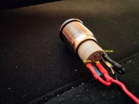
The photo seems to show the LED connected in parallel to the switch - did I get that right? - not in series as I suggested. A parallel connection would explain the relay remaining on which the switch on (i.e. shorting the LED) or off (leaving the LED in circuit, in which case the LED would be on).
Boy I feel ashamed, sometimes I can be dense. I get it and understand where I went wrong. It's been a long day. I got hooked on the idea of anode/cathode and pins, and wasn't even thinking about series vs parallel lol. Switch is functioning as desired now.
On a slightly related note, despite having a labeled anode and cathode, the LED on my switch functions bi-directionally on my DMM, certainly added to my confusion trying to come up with a solution earlier.
@alexcp you are a patient saint. Tomorrow I will wire up the input wire and get to listening.
On a slightly related note, despite having a labeled anode and cathode, the LED on my switch functions bi-directionally on my DMM, certainly added to my confusion trying to come up with a solution earlier.
@alexcp you are a patient saint. Tomorrow I will wire up the input wire and get to listening.
Meanwhile, another Omicron is live:


Quote from the builder:
Quote from the builder:
Built an Omicron on a breadboard. Plugged it into my DAC instead of my AD8397 based headamp. Could not measure the distortion - the measurements from the DAC output and from the Omicron's output are identical (0.00033%, measured by Cosmos ADC). Worked right after assembly, no debugging or adjustment was required. Sounds easy and relaxed, with precise bass. Will compare Omicron with my composite (NE5532+LT1210) headamp, but even now it is clear that the sound is good.
We are up and running! I haven't plugged in headphones yet, just listening to it as a preamp right now, and it sounds fantastic! I will give a more thought out review later on, but my initial impressions are that this is absurdly clean, the bass hits harder than my Krell KSA5 clone w/ alex's mods, all around I am very impressed and pleased.
Protection circuit definitely functions, while adjusting volume a few min ago there were a couple of moments where the audio cut and protection had clicked on/off. Not sure what would have caused any sort of spike, as long as protection works right?


Protection circuit definitely functions, while adjusting volume a few min ago there were a couple of moments where the audio cut and protection had clicked on/off. Not sure what would have caused any sort of spike, as long as protection works right?
This amp is fantastic, I've been listening away and taking notes for a better review, spent a few hours last night playing games with it, worked wonderfully. It really blows all of my other headphone amps and line amps out of the water. The clarity is surreal.
I've run into one oddball situation, a single track, at higher volumes will engage the protection circuit momentarily. Say at 0:51s it engages protection, I can rewind a few seconds, and it will engage at the same timestamp. Turn the volume down some, and it doesn't engage. Audibly the volume being output from headphones at the time is not painfully loud, and similarly when used as a preamp the same track isn't audibly too loud from the speakers. I've listened to quite a wide variety of music on this already, and thus far it's just this one track that causes this. One of the amps I am building is a gift for my brother and will be shipping it to him, so I'd like to at least understand this better and maybe troubleshoot a bit to see what could be the cause.
Admittedly I haven't opened up the amp to check anything while it's occurring, but my thoughts were to hook my DMM up to the output and watch the DC offset while playing the track in question. Another thing I was thinking about trying was pulling the pin on PGOOD to see if somehow that is getting in the way (thinking along the lines of 2k2 resistor not being enough for me as we saw the other day).
Appreciate any thoughts or ideas on this, happy to share the file in question, I tried listening to it on youtube, I couldn't recreate the scenario there, but not a fair comparison really. The track itself is 44/16 FLAC from the studio, trying with a 96/24 FLAC of the same track from the same studio, same thing. Later this afternoon I will test out my ideas of watching the outputs offset while recreating, as well as trying to remove PGOOD from the equation.
The first point I notice it is 0:13s, then 0:37s, 0:43 through 0:51s. Seems to happen fairly frequently on the track.
That I am aware of, there aren't too many releases/masters of the album, I've tried the Atlantic/Crush Music web release in 44/16 and 96/24, as well as the Atlantic Japanese Retail CD. All 3 have the same oddity. I'm playing with Foobar2000, WASAPI, directshared, doesn't seem to matter on output device. MPC-HC using a different audio renderer etc, same thing. DAC is a Topping D10s. It'll take a few hours, but I will see if my Schiit Modi 3 has any affect.
That I am aware of, there aren't too many releases/masters of the album, I've tried the Atlantic/Crush Music web release in 44/16 and 96/24, as well as the Atlantic Japanese Retail CD. All 3 have the same oddity. I'm playing with Foobar2000, WASAPI, directshared, doesn't seem to matter on output device. MPC-HC using a different audio renderer etc, same thing. DAC is a Topping D10s. It'll take a few hours, but I will see if my Schiit Modi 3 has any affect.
I've encountered a very similar sound source.
In my case the power amp's DC detection circuit worked.
Upon inspection, the cone of the right channel woofer slowly rocks back and forth.
Normally, when a DC component appears suddenly, harmonic components are generated in the audible band, causing an abnormality, but I did not hear anything. I checked with multiple CDs and they all had the same problem. It seems that there was a problem with the recording or mastering equipment on the production side.
This is the first movement of Brahms Violin Sonata No. 1 by Viktoria Mullova of Philips sound source. Around 06:45
It seems to be a similar situation here. The track in question has a large infrasound component. In an audio editor, it is visible as the mean deviating from zero:

and even more obvious if you filter out everything audio (i.e. 20Hz and above):

If you zoom in around 0:51 time code:

you see a large positive offset.
The offset is visible in real time at Omicron's output:

Naturally, Omicron's protection switched off the load - it does its job.
We see a few ways of dealing with this:
1. Do nothing and avoid this particular track (BTW in addition to what's discussed above, it clips a lot):

2. Adjust the window of allowable DC from +/-80mV to, say, +/-160mV by changing two resistors (R53 R54) from 100 ohm to 200 ohm.
3. Increase time constant of the protection's input LPF by increasing the values of C41-C44.
4. A combination of (2) and (3) above.
I'd suggest (2) as the easiest and least intrusive option. Note that any of (2), (3) or (4) would slow down the protection's triggering in case of a genuine fault.
and even more obvious if you filter out everything audio (i.e. 20Hz and above):
If you zoom in around 0:51 time code:
you see a large positive offset.
The offset is visible in real time at Omicron's output:
Naturally, Omicron's protection switched off the load - it does its job.
We see a few ways of dealing with this:
1. Do nothing and avoid this particular track (BTW in addition to what's discussed above, it clips a lot):
2. Adjust the window of allowable DC from +/-80mV to, say, +/-160mV by changing two resistors (R53 R54) from 100 ohm to 200 ohm.
3. Increase time constant of the protection's input LPF by increasing the values of C41-C44.
4. A combination of (2) and (3) above.
I'd suggest (2) as the easiest and least intrusive option. Note that any of (2), (3) or (4) would slow down the protection's triggering in case of a genuine fault.
Last edited:
That was fast! I didn't even think to open it in audacity. I'm not sure I will make any changes as it's preferential to have the protection circuit do it's thing. Not too surprised it clips a lot, loudness war these days and all that.
Thanks so much! I'll be back tomorrow with a review on this beauty.
Thanks so much! I'll be back tomorrow with a review on this beauty.
- Home
- Amplifiers
- Headphone Systems
- Omicron, a compact headphone amp with -140dB distortion