? Isn this too much.the maximum output voltage of 9.52Vp-p
Given that I am not using any preamplifier, the output voltage could even be a little higher, but this is also fine.
With 6S4P and passive I/V I had even 15Vp-p. Later I lowered it to 8Vp-p when I transferred it to the grounded grid.. With 6HM5(grounded grid) I had 7Vp-p. With tubes, sometimes there is no other choice, but this is a different story. Ti(BB) even suggests that the I/V stage has a higher gain than necessary due to extracting the maximum from the dac i.c. itself.( this especially applies to new generation DACs such as the PCM1794)
With 6S4P and passive I/V I had even 15Vp-p. Later I lowered it to 8Vp-p when I transferred it to the grounded grid.. With 6HM5(grounded grid) I had 7Vp-p. With tubes, sometimes there is no other choice, but this is a different story. Ti(BB) even suggests that the I/V stage has a higher gain than necessary due to extracting the maximum from the dac i.c. itself.( this especially applies to new generation DACs such as the PCM1794)
Last edited:
Wait a bit for my sound review, but honestly all my dreams about tubes in DAC disappeared after the I/V with AD811.Will be funny to see how it sonically compares to the ECC88 based one.
I can't say that it was my fault, but a project where I tried to get the maximum out of the tubes in the DAC itself, and that came after the AD811, which I used about 15 years ago for first time.I am crying....your fault !
As far as I know, I was the only one who used the grounded grid as I/V, which is the only proper way to use tubes as I/V. For this purpose, I also developed a low-noise HV regulator. I could say that for me it was an adventure where I learned a lot about tubes and HV power supplies, and along the way I helped with the creation of some excellent tube phono stages.
However, every technology has its peak, although I believe that good results can also be achieved with expensive tubes and complicated circuits which would certainly not be DIY friend as well as my circuit with 6HM5..
Likewise, the ECC88 should outperform any classic VFA op amp as an I/V if properly implemented.
The AD811 is something else and let's not confuse it with the classic VFA op amp.
Last edited:
I can try. I have an E188CC Philips 1973 (NIB). A friend sent me some NOS tubes to try too : 6DT8 Telefunken; 6922 Siemens origin, some 6922 british + dutch+ Siemens origins.
Is the virtual ground is keeped with the VFA op ? It is a plus for dac i/v job, no ?
Hey maybe Patrick from Xenaudio will make a discrete one !
Also with tubes, people often uses at the same time tube rectification and it impacts the sound as well. But I agree, the best subjective sound is th etarget whatever SS or tubes... let choose the best at the end. Have you tried active rectifier chip too in spite of rectification diode and snubers ?
Last edited:
I think that most of the amplifiers for max power have input signal of 1V (probably rms... because it is in most cases not clear, not stated...)Given that I am not using any preamplifier, the output voltage could even be a little higher, but this is also fine.
With 6S4P and passive I/V I had even 15Vp-p. Later I lowered it to 8Vp-p when I transferred it to the grounded grid.. With 6HM5(grounded grid) I had 7Vp-p. With tubes, sometimes there is no other choice, but this is a different story. Ti(BB) even suggests that the I/V stage has a higher gain than necessary due to extracting the maximum from the dac i.c. itself.( this especially applies to new generation DACs such as the PCM1794)
So the output stage with potentiometer acting as compessor-limitter with huge attenuation. In the same time adding to the source output resistance. That larger part of pot in series with the AD811. Can also with input capacitance of the amplifier as filter...
.
Tube power amlifier, in most casess has smaller input signal for max power.
With this more than 9vp-p, You can drive for the example EL84
")
.
At least You can blow the speakers out if You forget to lower the pot after listeninig Gramophone with riaa preamp with standard output value...
.
With thw tubes is much more easier to obtain better, lower, more convenient output level with choice of tube with lower mju factor.
And/Or lower value of Riv reisistor.
.
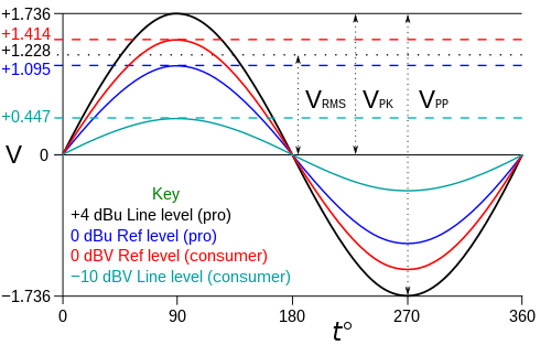
Standard output voltage for CD-player or DAC is 6Vp-p or 2.1Vrms and for the majority of solid state amplifier it is not enough to achieve maximum power, my DAC has 9.52V or 3.34Vrms, which is not a big difference . It should be taken into account that this is with a test signal of 1kHz at 0dB, digital recordings do not go exactly to 0dB, so it is always good to have a slightly higher output voltage.
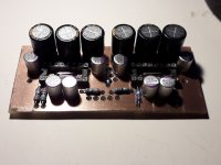
Today I received a lost shipment with two PCM1702, I hope I will be able to insert them into the DAC at the weekend. Then I will have 4 pieces per channel and the current will be 9.6mAp-p, so I will be able to reduce R2 to 1k, which will give me 9.6Vp-p at the output.
Attachments
Yes but that could be the problem because if You have say preamp with a gain of 10X (20db), which is also sort of standard in solid state, after that at 0db digital volume preamp will expand it to 20V RMS or 56.568Vp-p2 V Rms since half of the 80s if my memory serves me well
remember the first Philips cd players
.
This 2Vrms from CD players could directly drive solid state power amplifier even 50% of them are acheiving the full power with 1V rms... In that case the convetional L-pad pot could be OK because of not so big attenuation. It is important to see that the link working almost always in step down regime...
.
Not to mention tube gear with much more preamp gain, and much less sensitivity fir power amps...
.
So the construction and value of potentiometer is vital in these applications when signal is strongly attenuated all of the time.
Best soultion will be some transformer with secondary taps to swithcer, then some multi tap unductor, then bridged "T" resistor network (used exclousevly earlier in pro audio equipment)...
.
Some margins for potentiometer will be: minimum value is one where the sygnal loss is about 0.25db or preferably less. Because the pot value is LOAD to the pedecessor device (in parallel with input R of the next stage...)
Max value is when the pot in close to min range, when almost all value in series with source. That value is creating the filter in HF with input capacitance of next stage (and cab;e capacitance, connector capacitance...)
.
Last edited:
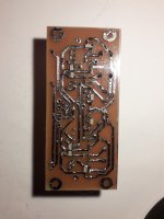
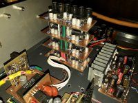
This morning, all 8 pieces of PCM1702 finally played. The sound is excellent, the installation of two more PCM1702 was worth it.
I made only the correction of R2 in the I/V stage due to the higher current of the dacs. The output voltage is 8.64Vp-p or 3.02Vrms.
I made only the correction of R2 in the I/V stage due to the higher current of the dacs. The output voltage is 8.64Vp-p or 3.02Vrms.
Attachments
It is true that a high output voltage of a CD player or DAC can cause a problem for a preamplifier with high gain, so that input should be fed directly to the buffer, bypassing the gain stage.Yes but that could be the problem because if You have say preamp with a gain of 10X (20db), which is also sort of standard in solid state, after that at 0db digital volume preamp will expand it to 20V RMS or 56.568Vp-p
.
This 2Vrms from CD players could directly drive solid state power amplifier even 50% of them are acheiving the full power with 1V rms... In that case the convetional L-pad pot could be OK because of not so big attenuation. It is important to see that the link working almost always in step down regime...
.
Not to mention tube gear with much more preamp gain, and much less sensitivity fir power amps...
.
So the construction and value of potentiometer is vital in these applications when signal is strongly attenuated all of the time.
Best soultion will be some transformer with secondary taps to swithcer, then some multi tap unductor, then bridged "T" resistor network (used exclousevly earlier in pro audio equipment)...
.
Some margins for potentiometer will be: minimum value is one where the sygnal loss is about 0.25db or preferably less. Because the pot value is LOAD to the pedecessor device (in parallel with input R of the next stage...)
Max value is when the pot in close to min range, when almost all value in series with source. That value is creating the filter in HF with input capacitance of next stage (and cab;e capacitance, connector capacitance...)
.
Today, all devices should have 2Vrms on their analog outputs and even phono preamplifiers, and then there will be no problems with input selection and different volumes. For example, McIntosh MP100 phono preamp can give up to 8Vrms max at its output, its tube brother MP1100 even more, 10Vrms max as well as REGA Aria MK3 MM/MC.
Now the question arises, is a preamplifier necessary with such voltages which can already drive the output stage without problems? Maybe as an input selector with a buffer and nothing more.
I, who only use a digital source, do not need even that, but only a quality potentiometer and DAC with low impedance output and sufficient voltage for drive amplifier.
MC and others doing wrong way with this. You are right The functional preamplifier is not needed. More it will act sort of disfunction,
as PRE-Silencer. Because All of the time it will exporting les ampitude then at the input. Also it is must in this case for "pra-amp" to have immediately on the input a POT. if not the case, huge input voltage can badly over-voltage the limit of the input level...
.
For my opinion based on listening analog pot is better then digital.
WOW !!!This morning, all 8 pieces of PCM1702 finally played. The sound is excellent, the installation of two more PCM1702 was worth it.
I made only the correction of R2 in the I/V stage due to the higher current of the dacs. The output voltage is 8.64Vp-p or 3.02Vrms.
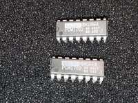
I see also PMD100. I simply cant understand how it is happened that this Pacific Microsonics fade out and stop making this legendary piece of IC...
This is the very good source of informations about the standards of line level signals
https://en.wikipedia.org/wiki/Line_level
https://en.wikipedia.org/wiki/Line_level
I think they were bought by Microsoft and discontinued the production of PMD100 and PMD200, unfortunately.WOW !!!
I see also PMD100. I simply cant understand how it is happened that this Pacific Microsonics fade out and stop making this legendary piece of IC...
The PMD100 is an excellent digital filter, it just requires separate supplies for VDD1 and VDD2 to achieve the DS specification.
Attachments

I compared the HDCD software plugin with PMD100 doing the same songs. After the Microsoft took over. And real PMD100 was much better...
Yes I was somehow stunned when measures current consumptions. (Even that they are written in the datas) One of them was a bit more than 100mA othe about 15-20mA...
I tried it with PCM56 and I am remember it was very good a different from other OS implementations. But I used diskrete OP class A.
Yes I was somehow stunned when measures current consumptions. (Even that they are written in the datas) One of them was a bit more than 100mA othe about 15-20mA...
I tried it with PCM56 and I am remember it was very good a different from other OS implementations. But I used diskrete OP class A.
- Home
- Source & Line
- Digital Line Level
- AD811 as I/V stage for current DACs (and test some other op amps including Burson Audio op amps as I/V)