Yes, there is indication on the board and it is wrong, which I find interesting. Both because one of my ribbon tweeters is wired backwards (black is positive) and also with both Speaker A and Speaker B (and also that of another S3A user online) the midrange speaker is wired with black having to be the positive, otherwise the speakers have no bass. I confirmed on the woofer side that e.g. red is the + but it is incorrect.
It was the other fellow who said they would end up in the dump. I hope to stop that from happening!
It was the other fellow who said they would end up in the dump. I hope to stop that from happening!
Why should it be wrong ? At least you should have equal polarities in both channels.
Wiring on the drivers itself should be unchanged by the repair workshop and can be
assumed to be OK as it came out from manufacture. You have to consider that tweeter
polarities are frequently reversed with certain forms of crossover.
The + symbol of post 191 does not apply. Red is "positive". Do not mess everything up.
You can safely assume that they did not open the driver side.
It's 'wrong' because for the full range driver, the black must be connected to the + on the green filter board, otherwise the sound is extremely thin - less bass than NS10s. It's placing the sub only and full range driver out of phase with each other.
Further - the tweeter in speaker B is reversed polarity re post 191 - I'm afraid it must apply for speaker B as it simply throws everything out of phase if connected the other way. I tested all the combinations in my studio and it's not subtle when they are out of phase.
The Adam Repair person connected it as would be logical - coloured on all three +tive filter board connections without actually listening. Again, this results in an out of phase sound. The black on the full range driver must be connected to +tive. This is also how it was on Speaker A, unlike how it was on Speaker B when I got it back.
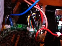
Here is another photo (from a different angle) from an old post from a user on Gearspace.com showing his Speaker A with the same configuration - the black is connected to +tive and red is on negative, same as mine.
Brown is on positive and black is negative in that case. This is the sub only woofer connection.
Further - the tweeter in speaker B is reversed polarity re post 191 - I'm afraid it must apply for speaker B as it simply throws everything out of phase if connected the other way. I tested all the combinations in my studio and it's not subtle when they are out of phase.
The Adam Repair person connected it as would be logical - coloured on all three +tive filter board connections without actually listening. Again, this results in an out of phase sound. The black on the full range driver must be connected to +tive. This is also how it was on Speaker A, unlike how it was on Speaker B when I got it back.
Here is another photo (from a different angle) from an old post from a user on Gearspace.com showing his Speaker A with the same configuration - the black is connected to +tive and red is on negative, same as mine.
Brown is on positive and black is negative in that case. This is the sub only woofer connection.
Attachments
Hi all, new to the forum but already picked up a lot of good info. I have a pair of P11A’s with working drivers but no LF on one side. Opened them up and bulging caps everywhere. In the process of swapping them out. Any tips on desoldering these? They seem pretty tricky to me compared to most recap jobs I’ve done in the past on other manufacturers products.
A copy of the schematic would come in handy just in case I lift any tracks and have to repair them/my problems lie further down the road than a simple recap.
A copy of the schematic would come in handy just in case I lift any tracks and have to repair them/my problems lie further down the road than a simple recap.
@as_audio Made a fresh account, so I am not able to send a PM directly, but I am looking for the schematics of the Artist 6. (tower speakers)
One of the 2 made a pop and the power cut off. So far, I have received the power and standby circuit from Adam directly. (willing to share with you if you would like)
So far, I have repaired the 4R7 2W safety resistor and the LNK364PN IC. This IC was obviously damaged.
When I reassembled the speaker I got power and audio again. After a few minutes a noise/hum started which was getting louder. I had to cut the power again to prevent any further damage. Could you point me in the right direction, and if possible with more schematics of the full speaker?
Many thanks in advance
If you could PM me I am able to reply to you.
Attachments

What I see on the picture looks like a switch mode power supply.
Perhaps it can be bought second source.
The glue you see, black in the meantime, is corrosive. it has to be
removed completely if possible. Look for damaged wires etc under
the glue.
With a SMPS it is essential to find all bad components.
Perhaps it can be bought second source.
The glue you see, black in the meantime, is corrosive. it has to be
removed completely if possible. Look for damaged wires etc under
the glue.
With a SMPS it is essential to find all bad components.
Thankyou for your quick reply.
After replacing the IC (U1) and the safety resistor (R1) In the stanby section I got power and audio again. However after a few minutes of playing a humm/noise started to come up. I am assuming there is something else failing in the other circuitry what caused the standby circuit to overload.
I will also remove the black adhesive to further inspect.
So in short:
Thanks a lot for the full schematics!
After replacing the IC (U1) and the safety resistor (R1) In the stanby section I got power and audio again. However after a few minutes of playing a humm/noise started to come up. I am assuming there is something else failing in the other circuitry what caused the standby circuit to overload.
I will also remove the black adhesive to further inspect.
So in short:
- Speaker went down with an audible pop. Volume was at like 20%
- Speaker started to work again by replacing U1 and R1 in "standby" section
- Now there still seems to be another issue which is causing the noise. It takes a few minutes before the noise starts to appear
Thanks a lot for the full schematics!
- Home
- Amplifiers
- Chip Amps
- ADAM Active Studio Monitor schematic diagrams help