@NeoTheOne , what I did for a temp setup was JB Weld some L brackets to a fused switched IEC inlet that had mounting tabs with screw holes. I can take a pic if you need it. Also if you have access to a 3D printer just make an L shaped bracket that's tall enough, then make an opening to snap in a fused IEC inlet. I could whip something up for you if you tell me what IEC inlet you want to use
A pic would surely help me a lot for reference.@NeoTheOne , what I did for a temp setup was JB Weld some L brackets to a fused switched IEC inlet that had mounting tabs with screw holes. I can take a pic if you need it. Also if you have access to a 3D printer just make an L shaped bracket that's tall enough, then make an opening to snap in a fused IEC inlet. I could whip something up for you if you tell me what IEC inlet you want to use

@badd99
This unfinished/in-progress project is based off the work by @badd99 in his post here:
https://www.diyaudio.com/community/...eapon-to-fight-the-jitter.192465/post-7569921
and his before and after sound comparison here:
https://www.diyaudio.com/community/...eapon-to-fight-the-jitter.192465/post-7570942
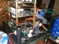
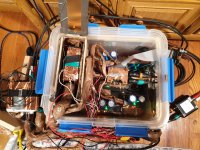
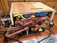
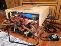
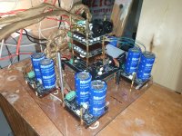
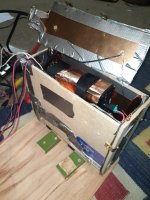
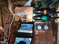
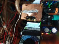
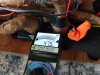
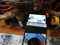
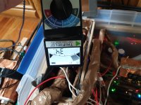
This project is unfinished, note the Topping A50s amp is positioned on top of the exterior r-core linear power supplies. Once I build a longer 12awg solid core GX16/2.1mm DC plug it will be moved from the left the right side of the unit where the analog output side is. Also, the wooden box inside the plastic container will be removed and the 5v linear power supply inside it will be stacked where the Topping amp is currently sitting, outside and far from the dac stack. The IanCanada PurePi/LifePO4 will be removed from the dac stack and placed where the wooden box / 5v linear power are currently sitting, a copper/aluminum barrier will be added to separate the PurePi/LifePO4 power supply from the dac.
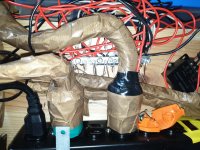
All solid-core conductors, 3x grounding wire / copper tape / ptfe tape DeoxIT D-series red (will apply Gold G-series version as well and maybe Shield-blue series), each individual copper shield / conductive wire has a direct grounding line to the grounding bus bar. There is still one AC cable I need to construct and replace in the Furman power strip and a USB cable that will have its own 5V UCconditioner power supply for the Amanero USB module, avoiding dirty power from the computer's USB output. In the end there will be a total of 5 UcConditioner boards.
Before @badd99 post on this forum (dac assembled as pictured in IanCanada's product photos) I only had about 60% - 70% of my current audio quality. His attention to grounding/isolation/insulation made a significant difference.
This unfinished/in-progress project is based off the work by @badd99 in his post here:
https://www.diyaudio.com/community/...eapon-to-fight-the-jitter.192465/post-7569921
and his before and after sound comparison here:
https://www.diyaudio.com/community/...eapon-to-fight-the-jitter.192465/post-7570942
This project is unfinished, note the Topping A50s amp is positioned on top of the exterior r-core linear power supplies. Once I build a longer 12awg solid core GX16/2.1mm DC plug it will be moved from the left the right side of the unit where the analog output side is. Also, the wooden box inside the plastic container will be removed and the 5v linear power supply inside it will be stacked where the Topping amp is currently sitting, outside and far from the dac stack. The IanCanada PurePi/LifePO4 will be removed from the dac stack and placed where the wooden box / 5v linear power are currently sitting, a copper/aluminum barrier will be added to separate the PurePi/LifePO4 power supply from the dac.
All solid-core conductors, 3x grounding wire / copper tape / ptfe tape DeoxIT D-series red (will apply Gold G-series version as well and maybe Shield-blue series), each individual copper shield / conductive wire has a direct grounding line to the grounding bus bar. There is still one AC cable I need to construct and replace in the Furman power strip and a USB cable that will have its own 5V UCconditioner power supply for the Amanero USB module, avoiding dirty power from the computer's USB output. In the end there will be a total of 5 UcConditioner boards.
Before @badd99 post on this forum (dac assembled as pictured in IanCanada's product photos) I only had about 60% - 70% of my current audio quality. His attention to grounding/isolation/insulation made a significant difference.
Attachments
-
 IMG_20240324_201849.jpg474.1 KB · Views: 69
 -
 IMG_20240327_093325.jpg727.9 KB · Views: 64
 -
 IMG_20240401_095216.jpg466.7 KB · Views: 60
 -
 IMG_20240422_235227_2.jpg191.3 KB · Views: 62
 -
 IMG_20240430_193109.jpg816.5 KB · Views: 63
 -
 IMG_20240430_220900.jpg659 KB · Views: 65
 -
 IMG_20240430_221129.jpg600.9 KB · Views: 62
 -
 IMG_20240430_221848.jpg603.4 KB · Views: 62
 -
 IMG_20240503_101828.jpg696.7 KB · Views: 70
 -
 IMG_20240324_201752.jpg597.3 KB · Views: 62
 -
 IMG_20240207_170904.jpg461.1 KB · Views: 63
 -
 1_IMG_20240501_111021.jpg577.6 KB · Views: 56
 -
 2_IMG_20240501_110806.jpg460.2 KB · Views: 52
 -
 3_IMG_20240501_111007.jpg525.4 KB · Views: 50
 -
 4_IMG_20240501_110703.jpg446.4 KB · Views: 49
 -
 5_IMG_20240501_110930.jpg408.1 KB · Views: 48
 -
 6_IMG_20240501_110428.jpg367.7 KB · Views: 46
 -
 7_IMG_20240501_110942.jpg447.9 KB · Views: 47
 -
 8_IMG_20240501_110830.jpg412.6 KB · Views: 52
 -
 IMG_20240205_153646.jpg364.8 KB · Views: 59
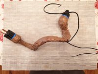
Any finished project I do is fully cased and grounded. That's just a board that's used to build a temporary circuit. It never has power plugged in unless someone is in front of itI Think thats Dangarious for saftey reasons you should put all mains components in a box, especially for kids and drunk people
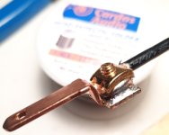
You obviously haven't built many projects, They can evolve in form for a while before you work out what sort of box is required, plus the IEC in the pic is clearly insulated at the back and goes into a shrouded screw block. It's only as "dangarious" as the user anyway, sbelyo has made his testing bed much more professionally than I bother to, i just zip tie the IEC to the board, but then there are no children or drunks in my workshop.I Think thats Dangarious for saftey reasons you should put all mains components in a box, especially for kids and drunk people
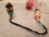
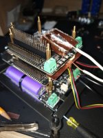
I just made this small add-on board for my personal use of my own DDDAC1794-MK3. It is an I2S switch with 5V relays. in this case between two sources, one with UF/L (like HDMI receiver) and the other for use with a source with flatcable/pins. it uses miniature 5V signal relays. Other Voltages are also possible of course.
You see it sitting on top of the FiFoPi.
Gerber to share is attached:


You see it sitting on top of the FiFoPi.
Gerber to share is attached:
Attachments
Last edited:
- Home
- Source & Line
- Digital Line Level
- Asynchronous I2S FIFO project, an ultimate weapon to fight the jitter