Hey there.
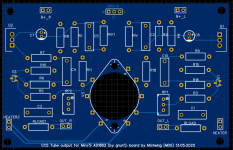
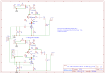
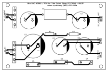
Made Gerbers for tube output, 6DJ8/6N23p/ECC88, ccs driven, with the schematic proposed by grunf on message #5200.
They are two boards, one for PSU, other one for music") I chose this way, you know, space is always limited within enclosures.
I chose this way, you know, space is always limited within enclosures.
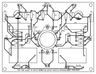
PSU is nothing fancy here, doing the CCS the hard work. Heaters are DC, not the finest DC, but it works pretty well on my other builds.
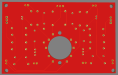
For the audio section, i preferred to have a hole hosting a noval socket, then you've to solder the pins. So you can choose different kind of tubes, it has not to be definitely the 6DJ8. In case of accomodating other tubes, modify the circuit accordingly (and the pinout, if necessary!).
The double in for heater power (one left, one right), leaves you the choice, where to locate the board into the chassis.
That should be everything (for the moment).
Of course you can use the board(s) for other projects (i'll install one on my CD player with TDA1541, now it has a lampizator SRPP schematic in it)!
PSU:
Audio board:
In case of errors, please answer me or contact me. Hope it helps someone, and, above all, thank you @grunf !
Made Gerbers for tube output, 6DJ8/6N23p/ECC88, ccs driven, with the schematic proposed by grunf on message #5200.
They are two boards, one for PSU, other one for music
I chose this way, you know, space is always limited within enclosures.PSU is nothing fancy here, doing the CCS the hard work. Heaters are DC, not the finest DC, but it works pretty well on my other builds.
For the audio section, i preferred to have a hole hosting a noval socket, then you've to solder the pins. So you can choose different kind of tubes, it has not to be definitely the 6DJ8. In case of accomodating other tubes, modify the circuit accordingly (and the pinout, if necessary!).
The double in for heater power (one left, one right), leaves you the choice, where to locate the board into the chassis.
That should be everything (for the moment).
Of course you can use the board(s) for other projects (i'll install one on my CD player with TDA1541, now it has a lampizator SRPP schematic in it)!
PSU:
Audio board:
In case of errors, please answer me or contact me. Hope it helps someone, and, above all, thank you @grunf !
Attachments
-
Gerber_Tube_CCS_AD1862_PCB_PSU_Tube_CCS_AD1862_1_2024-05-14.zip25.5 KB · Views: 11
-
 output3.png128.5 KB · Views: 62
 -
 output2.png98.6 KB · Views: 49
 -
 output1.png156.1 KB · Views: 72
 -
Gerber_Tube_CCS_AD1862_PCB_Tube_CCS_AD1862_1_2024-05-14.zip25.6 KB · Views: 9
-
 Schematic_Tube_CCS_AD1862_2024-05-14.png26.6 KB · Views: 70
 -
Schematic_Tube_CCS_AD1862_2024-05-14.pdf63.2 KB · Views: 14
-
 psu1.png75.2 KB · Views: 76
 -
 Schematic_Tube_CCS_AD1862_2024-05-14.png26.6 KB · Views: 62
 -
Schematic_Tube_CCS_AD1862_2024-05-14.pdf63.2 KB · Views: 11
Just a note, the Gerbers for the PSU are the same as the OUTPUT board.
Would this be the right transformer for this PSU board?
https://www.ebay.ca/itm/16265622811...6Sh7RH6vX2Y6St0xKRUwBNEozWhC|tkp:BFBM7PmP_O5j
Would this be the right transformer for this PSU board?
https://www.ebay.ca/itm/16265622811...6Sh7RH6vX2Y6St0xKRUwBNEozWhC|tkp:BFBM7PmP_O5j
Last edited:
Think you get too much b+ at 250V, an heavy load for the upper MOSFET... Better 150 max 160v. And only one 6.3V secondary (if you can find it)Just a note, the Gerbers for the PSU are the same as the OUTPUT board.
Would this be the right transformer for this PSU board?
https://www.ebay.ca/itm/162656228114?itmmeta=01HXVW3ZKFMX212BNA7P475308&hash=item25df111312:g:r6cAAOSw4EhgCDVy&itmprp=enc:AQAJAAAA4GXEId6IxY9wKEmpeWjV7eHZ5RjT1terFamKCq/ymNnw6mVT1mM9QYBwJYOey7cHyjGz1YoHOledC808j8831gd8caqeVaR9ogUNGrRrxewbO8hTUr6cnJcJGmYCXLxL9ff7wGEr/xgLDAoIB7EICXYPcNgI6jgBIm5c9076ljQ3b45FcSCxERk6V6UIUvRP0PwQzDVjdIe+8gbFWhE78wo7y1epQKckw7Ea2UVfXy/1KramwO/1kjsmfcY35dzDIWZdbASfw0UqRFUz6Sh7RH6vX2Y6St0xKRUwBNEozWhC|tkp:BFBM7PmP_O5j
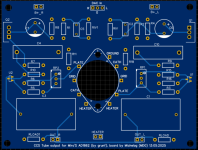
Ok, so, friends, please disregard my last upload #8261. I remade the boards for the tube output stage, with spacing fitting following BOMs. If possible i would ask a moderator to cancel previous uploads.
Schematics remain the same.
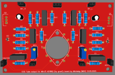
These 10uF Wima caps are huge, and so with more space perhaps you could fit some boutique cap. Now there's only 1 filament inlet, with the shortest path. I'll order them myself shortly.
Please let me know in case of further discrepancies.
Schematics remain the same.
These 10uF Wima caps are huge, and so with more space perhaps you could fit some boutique cap. Now there's only 1 filament inlet, with the shortest path. I'll order them myself shortly.
Please let me know in case of further discrepancies.
Attachments
-
 psu_render.png69.9 KB · Views: 27
 -
 PCB_AD1862-tube-output-B+-and-heater-power-supply_2024-05-16.png13.1 KB · Views: 33
 -
Gerber_AD1862_PSU_tube-output_2024-05-16.zip20 KB · Views: 7
-
BOM.zip20.1 KB · Views: 8
-
 PCB_PCB_Tube_CCS_AD1862_1_2024-05-16.png20.3 KB · Views: 29
 -
Gerber_Tube_CCS_AD1862_PCB_2024-05-16.zip27.1 KB · Views: 7
-
 Tube_audio_board.png88.3 KB · Views: 32
Setting up an AD1862 board without I/V and want to use one of the RPI/FifoPi Q3/Reclocker stacks that I have laying around for input to the DAC. I have soldered the ufl connectors on the AD1862 board for connection with the Reclocker. Do I still need to connect DL and DR? These supply points are not evident on on the FifoPi or Reclocker. I2S is still a bit of a mystery to me. I do have a JLSounds/AD1862/ Dark IV running and am liking the sound.
- Home
- Source & Line
- Digital Line Level
- DAC AD1862: Almost THT, I2S input, NOS, R-2R