Objective: Duplicate a vintage Tangent Acoustic RS2 using NOS/Currently available drivers
Intent is to a) first build a copy of the original speaker, and compare it vs the original. If it comes close enough then to experiment with alternate drivers for the 8" woofer, while utilizing the commercially available T27 tweeter.
Equipment on hand:
1) 2x Tangent Acoustic RS2 speakers
2) 2x T27 Tweeters, new from Falcon Acoustics
3) 2x NOS Audax 8" HD20B25J driver (the OEM driver for this speaker)
4) Umik-1
5) Dayton Audio DATS
6) Some free time here and there
7) Lots of enthusiasm
Plan:
1) Cabinet to be built as per the original spec, Of what I understand it's birch plywood with an MDF front baffle. No internal cross bracing, 1-1.5 inch foam padding all around. The drivers are mounted directly to the baffle. Status: In-work, Have opened up one speaker to assess crossover. will be utilized as main reference for measurements.
2) Crossover to be replicated using currently available components. Some interesting findings to share further in the thread.
3) Objective a) Speakers on hand, pending cabinet and crossover. Easier said than done.
4) Objective b) Have shortlisted 2 drivers (for the forum's review and feedback). File names in ( )
1) OE Audax 8" HD20 B25J specs: (HD20B25H - Catalog 1982)
2) Option #1: Audax HM210C0 (HM210C0 - Catalogue 1994) (comes very close with the fs at 30hz vs the 27 +/- 1 of the OE Audax)
3) Option #2: (slightly smaller) Scanspeak 18W/8424G00 (18w-8424g00)
Other drivers in consideration; Visaton BG20 (sitting by my desk), Visaton W200 (Also sitting here).
Disclaimer: I am not well versed in speaker determination, but I can match numbers better than my kid.
First up, Umik 1 freq response measurements of stock speakers. (1/6th octave smoothing).


Be right back. Bedtime for kids.
Intent is to a) first build a copy of the original speaker, and compare it vs the original. If it comes close enough then to experiment with alternate drivers for the 8" woofer, while utilizing the commercially available T27 tweeter.
Equipment on hand:
1) 2x Tangent Acoustic RS2 speakers
2) 2x T27 Tweeters, new from Falcon Acoustics
3) 2x NOS Audax 8" HD20B25J driver (the OEM driver for this speaker)
4) Umik-1
5) Dayton Audio DATS
6) Some free time here and there
7) Lots of enthusiasm
Plan:
1) Cabinet to be built as per the original spec, Of what I understand it's birch plywood with an MDF front baffle. No internal cross bracing, 1-1.5 inch foam padding all around. The drivers are mounted directly to the baffle. Status: In-work, Have opened up one speaker to assess crossover. will be utilized as main reference for measurements.
2) Crossover to be replicated using currently available components. Some interesting findings to share further in the thread.
3) Objective a) Speakers on hand, pending cabinet and crossover.
Easier said than done.4) Objective b) Have shortlisted 2 drivers (for the forum's review and feedback). File names in ( )
1) OE Audax 8" HD20 B25J specs: (HD20B25H - Catalog 1982)
2) Option #1: Audax HM210C0 (HM210C0 - Catalogue 1994) (comes very close with the fs at 30hz vs the 27 +/- 1 of the OE Audax)
3) Option #2: (slightly smaller) Scanspeak 18W/8424G00 (18w-8424g00)
Other drivers in consideration; Visaton BG20 (sitting by my desk), Visaton W200 (Also sitting here).
Disclaimer: I am not well versed in speaker determination, but I can match numbers better than my kid.
First up, Umik 1 freq response measurements of stock speakers. (1/6th octave smoothing).
Be right back. Bedtime for kids.
Attachments
Last edited:
After that, Ran some measurements on the drivers on hand (2x NOS Audax, the BG 20 and the W200) using DATS.
L to R: W200 - Audax #1 (t), Audax #1 again, BG 20, Audax #2 (t).
Used the SPL method to determine Vas. There was a slight learning curve so the screenshots are multiple. My paint skills are rudimentary but they get the job done.

First impressions, the BG20 came close but still far enough to not be considered 'worthy'.
Next up, money shot of the T27 tweeters:

Well, a Money shot.

Full disclaimer, this was my first time holding a famed T27 tweeter. Never considered how much weight/heft they carry. I thought it was all plate and no weight.
Then to the (not) fun part of opening up the speaker enclosure.

I had to unscrew the 8" driver to be able to lift the baffle out of the enclosure. The seal was really good around all sides. not entirely visible in this shot but if you look at the narrow gap between the Tweeter and the Woofer, you can see a crack in the MDF.
Re-secured the 8" driver using two screws to be able to lift the whole baffle.

Hello There!
The crossover is mounted directly to the MDF baffle with some rubber spacers and two wood screws. I'm not sure of the grey sealant around the corners so feedback/insights from folks who've opened such vintage speakers can advise.
A closer look at the crossover:

Everything looks fairly alright. Now to the hard part of figuring out the network/circuit.
I didn't want to disturb the original assembly of the speaker until I was absolutely sure I will be able to obtain all components of the circuit and build this out. So did not de-solder/disconnect anything. I did however, unscrew the crossover and insert a light to better see the circuit board and interconnects.
Here's a view from the other side of the PCB:

L to R: W200 - Audax #1 (t), Audax #1 again, BG 20, Audax #2 (t).
Used the SPL method to determine Vas. There was a slight learning curve so the screenshots are multiple. My paint skills are rudimentary but they get the job done.
First impressions, the BG20 came close but still far enough to not be considered 'worthy'.
Next up, money shot of the T27 tweeters:
Well, a Money shot.
Full disclaimer, this was my first time holding a famed T27 tweeter. Never considered how much weight/heft they carry. I thought it was all plate and no weight.
Then to the (not) fun part of opening up the speaker enclosure.
I had to unscrew the 8" driver to be able to lift the baffle out of the enclosure. The seal was really good around all sides. not entirely visible in this shot but if you look at the narrow gap between the Tweeter and the Woofer, you can see a crack in the MDF.
Re-secured the 8" driver using two screws to be able to lift the whole baffle.
Hello There!
The crossover is mounted directly to the MDF baffle with some rubber spacers and two wood screws. I'm not sure of the grey sealant around the corners so feedback/insights from folks who've opened such vintage speakers can advise.
A closer look at the crossover:
Everything looks fairly alright. Now to the hard part of figuring out the network/circuit.
I didn't want to disturb the original assembly of the speaker until I was absolutely sure I will be able to obtain all components of the circuit and build this out. So did not de-solder/disconnect anything. I did however, unscrew the crossover and insert a light to better see the circuit board and interconnects.
Here's a view from the other side of the PCB:
Some shots of the components on the crossover (relevance follows shortly, click on thumbnails for bigger view)


And I got to sketching the circuit out.
It's been over 15 years since I've last traced a circuit and it wasn't easy. Folks here really make it look easy.
I was able to identify the 27 Ohm resistor in the middle of the circuit with the red-violet-black-silver stripes. The green Caps were kind enough to have their values written on them.
The caps in the top left with the color bands seem to be a 1uf +/- 20% at 250V each (2 of them).
The inductors will have to be measured separately. I did get a reading off them with DATS.
Struggling to put the circuit together. I did what anyone else with my limited processing capabilities would. I googled it.
I inevitably went back to the thunders site for Tangent speakers and found the following picture of the TM1

Hold on. That looks awfully familiar from a x-over placement perspective. Same number of components. Could it be?
Then I looked (longingly and with tons of gratitude) to an image of a crossover circuit posted by one Colin Royle in 2006

And it came together really well!
However, there are some differences that I noted, and would need help figuring out as well as to Why the changes?
C1 = 50uF (matches TM1/TM3 Circuit above)
C2 = 6uF (matches TM1/TM3 Circuit above)
C4/C5 = 1uF + 1uF in parallel? instead of the 1uf + 2.2 uF
C6/C7 = 2.2uF +2.2uF in Series? (Values match the circuit above)
R1 = 10R/7W 10% (matches circuit)
R2 = 15R/10W 10% (also matches)
R3 = 27R/5W 10% (also matches).
Now for the inductors. I used calibrated DATS to measure the inductors directly installed in the circuit. Is this acceptable practice? Or should I de-solder them to get an accurate readout?
What I measured vs the circuit
L1 = (0.6325 mH, DCR: 0.4198 Ohms). Circuit is at 0.62, close enough.
L2 = (0.6154 mH, DCR: 0.6445 Ohms). Circuit is at 1.088, off by 40%
L3 = (0.3673 mH, DCR (0.2898 Ohms). Circuit is at 0.392, close enough.
This is my current impasse that I seek guidance upon.
I'm looking to order the components and put together a basic cross-over for swapping out the original crossover for testing.
Spending a few hours on electronic component stores, I've managed to get the Rs and the Cs confirmed available for shipping.
Q2: Can I swap the 1uF + 1uF and the 2.2uF+2.2 in parallel or series for an equivalent cap? IIRC Caps in series reduce, in parallel increase/add up.
Thank you for viewing all this information and taking the time to guide me!
I inevitably went back to the thunders site for Tangent speakers and found the following picture of the TM1
Hold on. That looks awfully familiar from a x-over placement perspective. Same number of components. Could it be?
Then I looked (longingly and with tons of gratitude) to an image of a crossover circuit posted by one Colin Royle in 2006
And it came together really well!
However, there are some differences that I noted, and would need help figuring out as well as to Why the changes?
C1 = 50uF (matches TM1/TM3 Circuit above)
C2 = 6uF (matches TM1/TM3 Circuit above)
C4/C5 = 1uF + 1uF in parallel? instead of the 1uf + 2.2 uF
C6/C7 = 2.2uF +2.2uF in Series? (Values match the circuit above)
R1 = 10R/7W 10% (matches circuit)
R2 = 15R/10W 10% (also matches)
R3 = 27R/5W 10% (also matches).
Now for the inductors. I used calibrated DATS to measure the inductors directly installed in the circuit. Is this acceptable practice? Or should I de-solder them to get an accurate readout?
What I measured vs the circuit
L1 = (0.6325 mH, DCR: 0.4198 Ohms). Circuit is at 0.62, close enough.
L2 = (0.6154 mH, DCR: 0.6445 Ohms). Circuit is at 1.088, off by 40%
L3 = (0.3673 mH, DCR (0.2898 Ohms). Circuit is at 0.392, close enough.
This is my current impasse that I seek guidance upon.
I'm looking to order the components and put together a basic cross-over for swapping out the original crossover for testing.
Spending a few hours on electronic component stores, I've managed to get the Rs and the Cs confirmed available for shipping.
Q2: Can I swap the 1uF + 1uF and the 2.2uF+2.2 in parallel or series for an equivalent cap? IIRC Caps in series reduce, in parallel increase/add up.
Thank you for viewing all this information and taking the time to guide me!
Thank you for that! Any particular reason for that thickness? resonance ability?15mm. important.
dave
RE: cotton or wool felt, I am open to experimenting with different type of fills to see impact on sound performance.
To make progress, I tested my measurements in XSIM: I used the measured values of the inductors and not the rated/listed values from the TM1/TM3 circuit.
For C4/C5 I assumed a 2uF Capacitor.
The frequency crossover seems to be at 3000Hz/3kHz with a -13.44dB or a 2nd order?
Funny bit is if I change it to 3.2uF, the crossover drops to 2600hz (reverting to 1uF+2.2uF).

Looking at available inductors, I will have to go with 2x 0.62mH (For L1 and L2 in circuit, L1 and L3 in XSIM)
and a 0.390 mH inductor for L3 in circuit/L2 in XSIM

I can't tell the difference. Seeking what everyone's thoughts are before I hit order button across 3 different online stores (and eBay for the WAGO connectors).
For C4/C5 I assumed a 2uF Capacitor.
The frequency crossover seems to be at 3000Hz/3kHz with a -13.44dB or a 2nd order?
Funny bit is if I change it to 3.2uF, the crossover drops to 2600hz (reverting to 1uF+2.2uF).
Looking at available inductors, I will have to go with 2x 0.62mH (For L1 and L2 in circuit, L1 and L3 in XSIM)
and a 0.390 mH inductor for L3 in circuit/L2 in XSIM
I can't tell the difference. Seeking what everyone's thoughts are before I hit order button across 3 different online stores (and eBay for the WAGO connectors).
Any particular reason for that thickness?
John Greenbank (the designer) was adamany the thinner, braced plywood (and the square vent) was an important part of the speakers.
I learned a lot from him, and have taken the concept further.
dave
Thank you. I will order additional caps.Those 'Elcap' electrolytics are notorious for going bad; I'd replace them in your Tangents
Thank you. Extremely fortunate of you. If there are any insights that could help improve the RS2 design further, I can incorporate them into the cabinet build and compare vs the previous one. I was thinking higher density MDF for the front baffle?John Greenbank (the designer) was adamany the thinner, braced plywood (and the square vent) was an important part of the speakers.
I learned a lot from him, and have taken the concept further.
dave
The coils must be separated from the circuit for a proper measurement value IF there are more components making a loop from one side to the other side of the coil. If there is no loop, ie the coil is not connected on one end to anything else, then the AC inductance measurement will be accurate if using a calibrated meter.
@wolf_teeth Thank you. I will have to dismantle the crossover to be able to measure the coils cleanly in free air then. You just saved me a ton!
DATS is fairly accurate from what I understand. Looking at the circuit, L1 and L3 seem to be open since the terminals are not connected to an amplifer. L2 however has a resistor (R2) in parallel to it and then additional components around it (C1, R1, C2) in a bigger loop. This will have to be removed from the crossover to get a clear measurement.
DATS is fairly accurate from what I understand. Looking at the circuit, L1 and L3 seem to be open since the terminals are not connected to an amplifer. L2 however has a resistor (R2) in parallel to it and then additional components around it (C1, R1, C2) in a bigger loop. This will have to be removed from the crossover to get a clear measurement.
any insights that could help improve the RS2 design further
Have a look at my miniOnken designs. Inpired by the Tangents crossed with the style of an Audax diy Onken (15”) and the more advanced ones taking edge and baffle dtep diffraction shape seriously by impitating a teardrop (in the horizontal plane), with braces taken to extremes from the “sticks” John used. Those were inpired by this single result from Tappen and what B&W did with the first Nautilus series.
This is a small one, a single brace (plus the side vent construction makes for an extremly stiff panel).
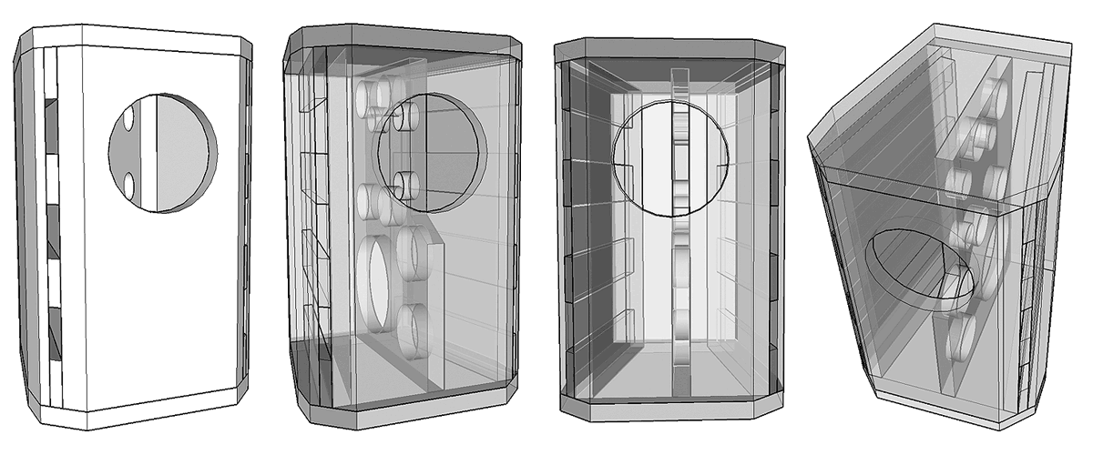
This enclosue has 27 x the volume and you can see th ebraces multiply significantly. You can see the relation to the Natilus (but a step further).
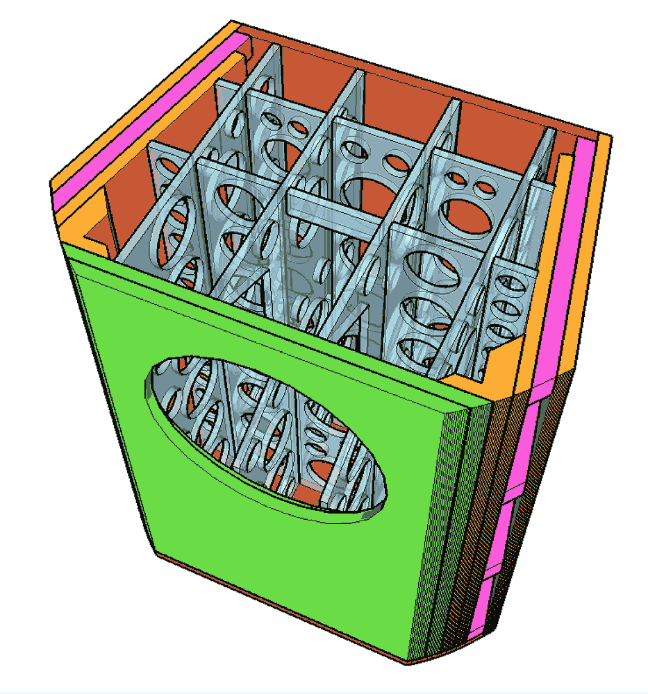
Not clear in these visualizations is that the (main) brace rigidly couples the back of the driver and the baffle to the baclk (and top & bottom) creating a much stiffer box.
This a development of the concept that John passe don of pushing any (potential) box resonances up high enuff that there is unlikely to ever be sufficiently continuous higher frequency notes to excite those (potential) resonances.
This likelihood graph is conceptual, the red curve (2nd order) easily supportable but there is enuff to suspect that the blue curve (4th orde) is more likely.
dave
DATS is fairly accurate from what I understand
But T/S measurements are questionable for anything but driver matching (parametersare guessed from the impedance curve instead of directly measured [ref: author]). Note that weather (temp, humidity, air pressure) means 2 drivers measured at different times are not directly comparable.
dave
@planet10 Thank you for taking the time to detail this information. Based on what you shared, I am considering if re-positioning the crossover to the bottom or side and bracing the baffle to the back of the speaker cabinet will have an impact.
The damage/crack to the baffle center between tweeter and woofer seems a relatively weak area, especially coz it's also supporting the crossover weight. Thoughts?
On the RS6, it was a cross brace/T-brace right behind the middle driver. But since I am looking to match external dimensions as the RS2, Most effort can be internal or in the material selection.
RE: T/S measurements, I did consider the temp/humidity factor and am trying to keep the measurements in fairly consistent environments. In this particular case, I have to measure the inductors to be able to re-build the crossover from new.
re-positioning the crossover to the bottom or side
Or even outside the box.
damage/crack to the baffle center between tweeter and woofer seems a relatively weak area, especially coz it's also supporting the crossover weight. Thoughts?
MDF. An issue i have seen in other Tangents. Never had that issue with plywood, but also rarely do i use a tweeter.
Inductor measures will not be affected by weather.
dave
Last edited:
that's literally Out of the box thinking. I will keep that option in mind depending on how 'good' the crossover looks once completed.
I am considering a thicker (or denser) MDF board to strengthen the baffle. Removing the crossover will also reduce that strain/load. Unsure if a thicker baffle will affect the sound performance (or a denser one for that matter). Thoughts?
I will keep that option in mind depending on how 'good' the crossover looks once completed.I am considering a thicker (or denser) MDF board to strengthen the baffle. Removing the crossover will also reduce that strain/load. Unsure if a thicker baffle will affect the sound performance (or a denser one for that matter). Thoughts?
Last edited:
Brief update: In the interest of saving time (and my old crossovers), I am considering purchasing both a 0.62mH and a 1.08 (1.1) mH inductor for the crossover at position L2.
Additionally I'll get a 2uF + 2x 1uF Capacitors for testing. (I'll double the qty so in case if they work better instead of 1x 2uF then I can use the 2x 1uF in the crossover).
Circuit attached for reference.
(Backstory from posts above: My measured inductance on L2 was 0.62 instead of the 1.088. The attached circuit is driving a KEF B200/1014 while I'm using the layout to drive a Audax HD20 B25J in a RS2 which seems to be using the same layout of circuit, just different values on L2 and C4/C5
Original plan was to de-solder the inductor from the old crossover and then measure it, but I'd keep that as a last resort if the 0.62 or the 1.1 mH don't work/sound the same).
Alternately, get an old RS2 pair and use the crossover from that for measurements.
Last edited by a moderator:
- Home
- Loudspeakers
- Multi-Way
- Duplicating a Tangent RS2 (My first DIY)